Moving in 3D Mode with Arbortext IsoDraw CADprocess
All objects (assemblies) in the drawing can be moved with the Arrow tool. First select the direction you wish to move them in. You can either move them on the X-Z plane or along the Y-axis. Either click on the Y-axis or on the X or Z-axis for the plane. The free axis is highlighted. If you have selected the X-Z plane, you can move all the assemblies in either X or Z-direction. Holding down the ALT key allows you to move the selected assemblies freely.
|
|
3D transformations, such as 3D Move, only apply to visible 3D objects by default. If you want 3D transformations to apply to both visible 3D objects and invisible parts inside of 3D objects, you must enable the CADprocess_TransformInvisible3DSubObjects preference setting. (See 3D Editing Preferences for instructions.) |
If you have previously created a free axis with one of the 3D Select axis tools, the blue free axis appears. Provided no other axis is selected, your selected assemblies or elements will be moved along this axis.
Use the selection rectangle to select all the assemblies in the drawing. Click the contour of an assembly. Hold down the mouse button and move the mouse. The drawing migrates on the axis as you move the mouse. The distance is displayed in the window bar at the bottom. The drawing will appear in its new position when you release the mouse button.
In the same way, you can also move assemblies you have selected. You can select the required assemblies using the object window or the Arrow tool.
Select the assemblies you require. Then click a contour of the selection with the arrow cursor. Move the selected assemblies to the required position while holding down the mouse button.
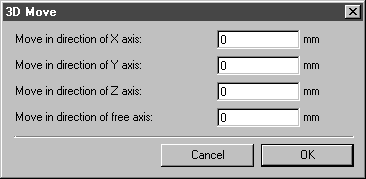
Holding down the SHIFT key when you click on the selection will result in the following dialog box appearing:
Enter the required values for the relevant axes. If you enter a positive value, the assemblies will be moved in the direction bearing the axis designation (X, Y, Z). If you enter a negative value, they will move in the opposite direction. If you have previously created a free axis (blue) with one of the 3D Select axis tools, you can enter a value under Move in direction of free axis. The free axis arrow/the line with the arrow defines the positive direction. If there is no additional axis, no value can be entered here.
Confirm your entry in the dialog box by clicking OK. The selection now appears in the new position on the axes. Clicking Cancel closes the dialog box without moving the selection.
| 3D object surface elements from files without structured import cannot be selected using the Arrow tool. Use the Arrow (+)  tool for these elements. However, smaller surface elements that form a larger 3D object surface are not individually selectable—even though you can see their borders. This is because the smaller surfaces are merged into the larger surface before the 3D object is rendered. |
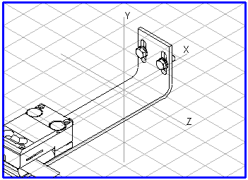
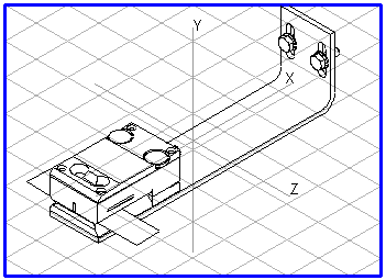
In the example shown, the drawing has been moved in positive direction along the X-axis.