Make the Relevant Area of the Obscuring Parts Transparent
The exercise now focuses on revealing the hidden parts spindle (spindle.114) and metal (metal.115) with countersunk screws (countersunk screw_IDR...) that are situated among the surrounding sections of the anchor plate (plate.111).
To ensure that, later on in the exercise, you can see whether the hidden parts are within the area to be made transparent the display mode needs to be changed.
1. Click on the symbol for
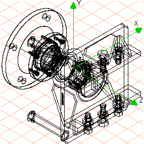
Wireframe
display mode.
The drawing now appears on the screen as indicated in the figure.
2. Click the symbol for the
3D transparent free shape
.
The cursor changes to a lasso

.
3. You now need to select the parts where areas are to be made transparent.
Hold down the CTRL key.
The cursor changes to an arrow

cursor.
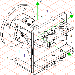
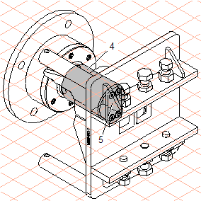
4. Click in the area of the anchor plate (1, plate.111). Holding down the SHIFT key, click in the area of all the parts that form the anchor plate (1, plate.111) one after the other. Also click in the area of bolt (2) and nut (3) situated in front of the metal and spindle.
HLR display mode has been used in the figure to make it easier to assign callouts to the relevant parts.
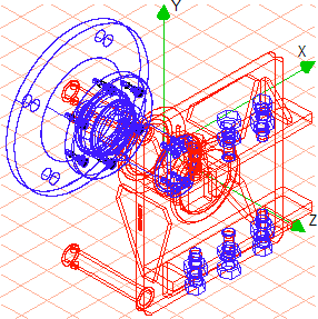
The selected parts are depicted with red contour lines.
5. Release the CTRL and SHIFT keys once all the parts have been selected.
The cursor changes back to a lasso
. The transparency tool is active.
The drawing needs to be enlarged so that the area to be made transparent can be selected more accurately.
6. Hold down the CTRL+ALT keys.
The cursor changes into a magnifying glass with a plus sign.
Click with your mouse on the area to be made transparent.
Release the CTRL+ALT keys.
The cursor changes back to a lasso
. The transparency tool is active.
7. Holding down the mouse button, move your mouse.
Define the boundary within which the selected parts are to be made transparent.
8. Set the boundary so that it encompasses the outer contour of the spindle and metal.
Change to
Rendering
display mode.
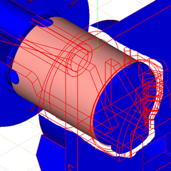
You can now see whether the boundary for the transparent parts is sufficient.
The figure depicts the approximate look of the boundary.
9. The drawing can now be converted to a 2D illustration for final editing.
To do this, click on the
Convert to 2D illustration
symbol.
The drawing is converted and appears in a new untitled window.
10. Select the new untitled window containing the converted file from the list of open files in the Window menu.
The window is brought to the front and becomes the active window.
11. Save the drawing as spindle_trans_2D.idr.
12. You can now highlight the hidden parts spindle (4) and metal (5). To do this, use the Bézier

tool to draw a path (
Pens-
No pen) over the outer contour lines of both parts and specify a fill. The filled area must then be sent to the back so that the contour lines are visible.
The figure depicts the drawing with a gray fill. The file spindle_trans_2D.idr with the completed drawing can be found in the Arbortext-IsoDraw-install-path\Tutorial\Tutorial CADprocess folder.