Create an Axis and Explode Parts
The axis for the grease nipple with protecting cap does not lie on one of the coordinate system axes. This axis must be created before the parts can be exploded for the appropriate view.
1. You can create the axis using the
3D Select axis (through the origin) 
tool.
Click on the symbol for
3D Select axis (through the origin) .
The axis selector symbol appears next to the cursor.
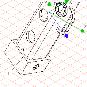
2. Now click on contour (1) on the left of the thread plate (103_thread plate...).
This element has the same orientation as the required axis.
When you have hit the element, a blue line appears briefly and an additional blue axis appears in the coordinate system. The direction of the axis matches that of the selected element.
| The additional free axis is now active. All selected surfaces and objects can now be moved along the axis. |
3. Change to
Wireframe
display mode.
4. Select the
Arrow
tool and then select the grease nipple (
116_grease nipple...). While holding down the SHIFT key, select the protecting cap (
117_protecting cap...).
| When the arrow  cursor is positioned over a part, object information is displayed. This makes it easy to locate a part. |
Once the parts have been hit, their contour lines are depicted in red.
5. Click on the symbol for the
Explode assemblies
tool.
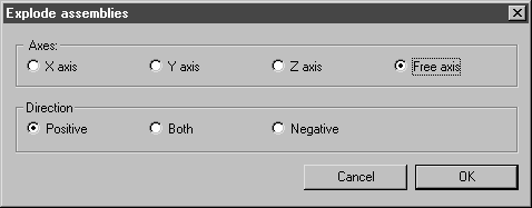
The following dialog box appears.
6. Click the buttons next to Free axis and Positive.
7. Confirm the settings by clicking OK.
Both parts are exploded. They remain selected.
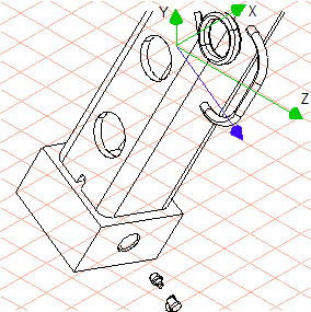
8. Move the arrow cursor to the selected parts. Holding down the mouse button, drag the parts away from the thread plate until they are a sufficient distance away.
The drawing now appears in HLR display mode as depicted in the figure.
9. The drawing can now be converted to a 2D illustration for final editing.
To do this, click on the
Convert to 2D illustration
symbol.
10. Select the remove hidden lines option in the subsequent 3D Projection-Set dialog and confirm by clicking OK.
The converted drawing appears in the active drawing window.
11. Save the drawing as nipple_explo_2D.idr.
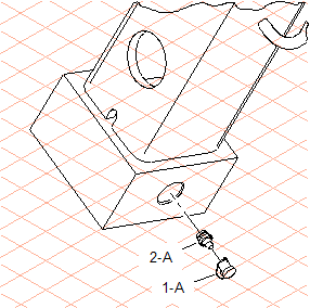
12. You can now complete the drawing using the tools in Arbortext IsoDraw CADprocess. Draw an outer thread suitable for the grease nipple and draw the center lines.
In the figure, the drawing has been enlarged, the mounting body has been depicted as a phantom part (thin lines only) with break lines and the spare parts have been assigned callouts. The file, nipple_explo_2D.idr, with the completed drawing can be found in the Arbortext-IsoDraw-install-path\Tutorial\Tutorial CADprocess folder.