Display the coordinate systems of a Design Analysis result.
Enter into command line
(load "fe_res_coor")
Or add this line to your customization file.
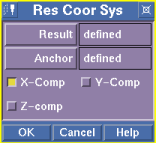
Loading this file will create a button "Res Coor Sys" in the toolbox.
With SolidDesigner 05.10 the coordinate system of a result was displayed by default within the external results window. If you switched to selected results components (e.g. Sigma X) there was always the possibility to compare the display within the results window with respect to the coordinate axis system displayed too.
With SolidDesigner 06.00 the Results display got integrated into SolidDesigners normal Viewports with the possibility to switch on/off the global axis system, the special result coordinate system was no longer available.
If you position a part or an assembly the (hidden) coordinate system of that part or assembly is no longer parallel to the global coordinate system displayed in the viewport. Such a case is shown in the image below.
In order to give the customer a method to display the coordinate systems of a result, a small tool got implemented, which allows visualization of single axis of a coordinate system.
If you look closely at the image above, you will see that the global Z-Axis and the X-Axis of the result are collinear.
With SolidDesigner 07.50 a local coordinate system is attached to all results display. It looks the same as the coordinate system of a workplane, i.e. the local U-Axis of the result is meant if there is a X-Component selected from the menu.
| © 2024 Parametric
Technology GmbH (a subsidiary of PTC Inc.), All Rights Reserved |