Layout QuickView Mode
Overview
High precision layout is the only way to display a layout in Creo
Elements/Direct Modeling and to get 3D info into the 2D world. This
calculation is very time and memory consuming and therefore inhibits
performance. To overcome the problems in situations where a high precision
layout is not required (e.g. display in Creo Elements/Direct Modeling,
dumpscreen accuracy is enough etc.) Creo Elements/Direct Modeling supports
layout functionality directly on the faceted model. This mode is called
"QuickView". Instead of calculating the layout, and displaying the 2D
geometry, Creo Elements/Direct Modeling produces layout views by displaying
the 3D object in the specified views. The silhouettes are derived from the
facets model when the layout view is drawn on the screen. The QuickView mode
takes therefore NO extra memory.
Activation
Enter into command line
(load "quickview")
Or add this line to your customization file.
This places two new buttons in the Creo Elements/Direct Modeling
toolbox.
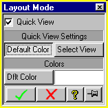
Description
One command in toolbox is called 'Layout Mode' and lets you switch on/off
the layout QuickView mode.
The second new command in toolbox one is called 'DWG-Frame' and lets you
define a workplane which is added to the drawing list of the QuickView port.
It is positioned in a way that it can be used to load/create a drawing
frame. The default-name of this workplane is
<layout-owner-name>/<layout-name>-FRAME
NOTE: This workplane is NOT connected to the layout. If you want to store
it as an MI-file together with the layout you have to do this
separately.
A QuickView port offers the following functionality :
- all view types are supported
- for section views Creo Elements/Direct Modeling automatically colors
the section faces
NOTE: This section face information is NOT passed to MI when
storing 2d-data of a calculated layout and not using the Creo
Elements/Direct Annotation module.
- 3D labels are displayed in a view if the normal of the label's display
plane and the view direction of the corresponding view are the same. 3D
labels CANNOT be added/positioned using the QuickView port. They must be
defined in an ordinary 3D port.
NOTE: 3D label information is currently NOT passed to MI when the
layout is calculated.
- the drawing list of the QuickView port can be unlocked.
- the default layout color can be customized
- the display mode can be specified for each view as:
- default color:
- the view is displayed in the layout default color
- part color:
- the parts in this view inherit the 3D part's color; especially
useful for assemblies with different colored parts
- shaded:
- the view is displayed as shaded model
- changing the display of hidden lines is implemented through face
transparency. The options 'HIDDEN NONE', 'HIDDEN DASHED', 'HIDDEN SOLID'
are realized through face transparency 0.0, 0.5 and 1.0
- the options 'TANGENT EDGES ON/OFF' have no effect on the QuickView
port
- dump screen is of course possible (use the change viewport background
color tool). For best results maximize the QuickView port before
dumping.
Limitations, hints and tricks
- Hints and tricks
- switching QuickView on and off
-
To avoid confusion and unexpected results you should ALWAYS work in
one mode. Don't mix layout ports and QuickView ports. For the same
reason don't mix calculated views and views displayed in QuickView
mode in the same viewport. To achieve a unique state ALWAYS start
with cleared views. The best way to achieve this is to update the
entire layout with the :CLEAR_VIEW option. If you wish to switch
from one mode into another follow these steps:
- clear the entire layout using the :CLEAR_VIEW option
- delete the corresponding port
- switch the QuickView mode
- recall and update the layout
- adding a drawing frame
- This is only possible in the QuickView mode. Press the "DWG-Frame"
button in the toolbox and identify the layout. Creo Elements/Direct
Modeling creates a new workplane, sets it current and adds it to the
QuickView ports drawing list. You then can create 2D geometry in this
workplane using ordinary 2D creation methods (including loading an
MI-file)
- scaling a drawing
- If you need to scale a drawing you have to scale the drawing
frame. It is not possible to scale the contents of the drawing.
- adding labels
- If you want to add text or labels to the drawing frame workplane
you first have to unlock the QuickView port's drawing list. You then
can add the labels directly in the QuickView port. Don't forget to
lock the drawing list again when you have finished your work.
If you wish to add labels to the 3D model you have to define them in
an ordinary 3D port. The labels are displayed in the QuickView port if
their display plane is parallel to a view.
- suppressing the magenta colored border of the layout
- Switch 'show constr' off in the show settings menu
- the layout viewport seems to be blank
-
- check whether 'show constr' is switched off
- update the layout with the :clear_view option
- there is a graphics problem which might lead to stitched or missing
silhouettes, especially for faces with a coarse facets resolution. In this
situation a facets refinement on the corresponding face often helps.
- there is no 'save environment support' for the QuickView mode.
- to transfer the layout to ME10 you have to switch QuickView off before
the layout is updated
- Labels and section face information displayed in the QuickView port
will NOT be transferred to MI when the layout is calculated (For sections
see NOTE above).
- the feedback in a layout viewport is displayed incorrectly until the
command is completed. (QuickView port and and ordinary 2D viewport).
- NEVER try to add 3D-labels to a section view
- NEVER use the drawing frame workplane for machining
- A section view is NOT updated automatically when its parts are
changed
- It is NOT possible to pick an updated view of a layout in QuickView
mode.
© 2024 Parametric
Technology GmbH
(a subsidiary of PTC Inc.), All Rights Reserved |