About Selecting Data
|
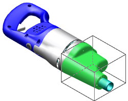
You can select one or more parts or annotations in the figure window for the loaded assembly. By default, selected parts are highlighted and surrounded by a bounding box. With Creo Illustrate’s smart selection method, you can refine the selection of a part to a surface or edge on that part—and then to a point on the surface or edge.
You can also drag the pointer over an area to select parts.
• To select all parts that are located fully within the selection box, drag from left to right.
• To select all parts that touch the selection box, drag from right to left.
|
|
You can set the Keep selection when switching between figures check box to keep the same sBOM parts selected when switching between or creating new figures.
You cannot select phantom parts in the figure window unless you press and hold the ALT key while making the selection. (Phantom parts have the Phantom style applied.)
Set options to enable or disable preselection, and secondary selection highlighting for 3D parts. For other geometry, it is enabled by default. You can set a smart selection filter to select that type of item. You can view a list of the items that are selected, and you can see a summary of the number of selected items in the status bar. You can also select or deselect all parts simultaneously, or, invert the part selection.