About the Datum Target Ribbon Tab
Datum Target is a contextual ribbon tab that appears when you place a newly created or select an existing datum target. The Datum Target ribbon tab lists all the defined properties of the selected datum target. You can use commands of other groups to modify the properties of the selected datum target.
The following groups are available in the Datum Target ribbon tab:
• References
The commands in the Reference group allows you to control the references that you use to create the datum target symbol.
Click the Reference command. The References dialog box opens. It lists the details of references that were used to create the selected datum target. You can modify the references of the selected datum target.
• Target Area
The commands in the Target Area group enable you to control the type of target area to use for the selected datum target.
It displays the target area that was previously used to create the datum target. You can specify the target area as, Point, Circular, Rectangular, or None. The specified target area symbol appears at the attachment point of the selected datum target.
◦ Point
When a new datum target symbol is created in a part or drawing, the Point option is used by default in the Target Area list. When this option is chosen, the x-style cross is displayed in the attachment point position.
In drawing, the x-style cross is displayed in the drawing plane.
In part and assembly mode, when the point of attachment of a datum target symbol is defined on a planar surface point, the x-style cross is displayed on the plane of the selected planar face. For all other cases, the x-style cross is displayed on the annotation plane.
◦ Circle
When the circular option is chosen, the hatched circle describing the target area is displayed. The size of the circle is defined by the width edit box available in the Size & Reference group. The circle center is located in the attachment point position. In drawing, the circular target area is displayed only in those views where the circular target area lies in the view plane. Otherwise, the circular target area is not displayed.
The circular area located on the front model face is displayed only when the front face lies in the view plane (front view). In top and side views, the target area is not displayed because it does not lie in the view plane.
In part or assembly mode, when the attachment point for the datum target symbol is defined on the planar surface, the target area circle is displayed on the planar surface. For all other cases, the circle is displayed on the annotation plane.
◦ Rectangle
When this option is chosen, the hatched circle describing the target area is displayed. The size of the circle is defined by the width edit box available in the Size & Reference group. The center of the target area rectangle is located in the attachment point position.
In drawing, the rectangular target area is displayed only in those views where the target area lies in the view plane. Otherwise, the rectangular target area is not displayed.
In part and assembly mode, when the attachment point for the datum target symbol is on the surface point, the target area rectangle is displayed on the plane of the selected planar face. For all other cases, the rectangle is displayed on the annotation plane.
◦ None
With this option is selected, the target area is not indicated. The leader directly connects the attachment point with the datum target frame.
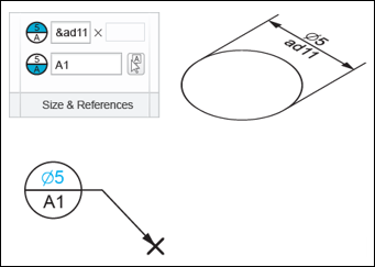
• Size & References
The commands in the Size & References group enable you to control the size of the associated target area and datum references for the selected datum target.
You can specify numeric values in the width and height in the boxes to define the size of the target area. Values that you enter in these boxes appear in the upper compartment of the datum target symbol.
Additionally, you can specify dimension call-outs preceded with & character in these value boxes. The dimension callout is used as parameter definition, and the referred dimension value is determined. This dimension value is displayed in the datum target symbol.
These value boxes made available based on the type of target area you specify. For Point and Circular target area, you can specify only the width value, which appears in the top compartment of the datum target symbol with the diameter sign. Similarly, for the Rectangle and None target area, you can specify both the width and height values, which appear separated by a x sign in the top compartment of the datum target symbol.
The datum reference box allows you to specify the datum reference string which contains the datum reference name followed by the index. Additionally, you can click and select an existing datum reference in the current assembly, part, or drawing.
When the datum reference string is defined in the edit box, the string is parsed in order to extract datum reference name and establish the correspondence between the datum reference name and model data.
During the parsing every continuous sequence consisting of characters A…Z, numbers 0…9 and underscore ( _ ) symbols is determined in the entered string. Every such a sequence is considered as candidate to the name of the datum reference existing in the model. Such a character sequence is referred as datum reference sub-string.
For example in the datum reference string shown, the single-letter datum reference sub-string A is determined.
For the datum reference sub-string, the search is performed in the model in order to detect the existing datum reference with the same name as defined in the sub-string. When an existing datum reference with the name matching to the detected sub-string is found, the parametric correspondence is established between the datum reference in the model and datum reference sub-string used for the datum target definition. When the parametric correspondence is established between the datum reference in the model and datum reference sub-string, the sub-string in the datum reference edit box is emphasized by green color.
When the correspondence is established, such a parametric correspondence provides you with the possibility to automatically update the datum target when the name of the datum reference mentioned in the datum target is updated. When datum tag A in the model is renamed to C, the datum target symbol is automatically updated because the typed datum reference sub-string has a correspondence with the model data. The updated datum reference is displayed within the datum target symbol and is available in the datum reference edit box.
When the datum reference defined for the current datum target symbol is considered as syntactically or semantically incorrect, the datum reference is highlighted as red wavy line.
The semantically incorrect datum target symbol is highlighted in the graphics area
A tooltip is available when the edit box containing the incorrect string underlined by red wavy line is clicked.
• Area Size Display
The commands in the Area Size Display group enable you to define the location of the target area size defined by the width and height boxes in the Size & References group.
◦ Click the Inside to define the target area size within the upper compartment of the datum target symbol. This option is chosen by default for every newly created datum target symbol.
◦ Click the Outside to define the target area size outside the datum target symbol. The target area size appears with a separate leader connected to the center of the upper compartment of the datum target symbol.
• Movable Datum Target
The commands in the Movable Datum Target group enable you to move the datum target symbol.
When you click Movable Datum Target, the selected datum target symbol appears as a symbol that can be moved with its tip attached to the leader end point, instead of the conventional datum target symbol. By default, the movable datum target symbol appears horizontally attached to the leader end point, or to the elbow end point if the leader elbow is available. The Rotate Symbol is active only after you click Movable Datum Target. Click the Rotate Symbol to rotate the movable datum target symbol by 90 degrees, around its tip, in the clockwise direction.
The initial orientation of the datum target symbol depends on the leader orientation. The symbol orientation is chosen to preserve the obtuse angle between leader and the symbol.
As the symbol rotation is performed around the symbol tip which is attached to the leader or elbow, the leader and elbow remain unchanged during the movable datum target symbol flipping.
Click the active Movable Datum Target, so that the selected datum target symbol appears as the conventional datum target symbol instead of the movable symbol.
|  For the datum target symbol without a leader, the movable symbol appears with its tip at the location of the selected datum target symbol. |
• Leader
The commands in this group enable you to control the leader display for the selected datum target symbol.
◦ Arrow Style — The list provides the options to choose the arrow style for leaders of the current datum target symbol. The Arrow Style list is enabled for datum target symbols with leaders. When the No Leader option is chosen the list is not available. A similar list is available in the Format tab, and the same options are available in the list. When a new datum target symbol is created, the None option is chosen for the Arrow Style by default regardless of the Target Area type.
◦ Straight Leader — When this option is chosen, the straight leader with no elbow is displayed connecting the datum target symbol with the target. When the straight leader is not used, the leader is oriented along the virtual line connecting the target area point or target area center (for rectangular and circular target area) with the center of the datum target frame.
◦ No Leader — When this option is chosen, the leader is not displayed. However, the chosen target area is still available at the attachment point; therefore the datum target symbol cannot be considered as unattached.
◦ Near-Side — This option enables you to use solid line for the leader, indicating the applying the datum target symbol to the near (visible) side of the surface where the datum target symbol is attached.
◦ Far-Side — This option enables you to use a dashed line for the leader. It enables you to apply the datum target symbol to the farthest side of the surface to which the datum target symbol is attached.
| • You can use the Near-Side and Far-Side options only when the selected datum target symbol has the leader style as Elbow Leader or Straight Leader. If you use the Far-Side option for a datum target symbol Elbow Leader selected as the leader style, the elbow appears as a solid line and the leader appears as a dashed line. • As the datum target symbol application is displayed by modifying the leader style, the Near-Side and Far-Side commands are enabled only when the Straight Leader option is chosen. When the No Leader option is selected, the Near-Side and Far-Side commands are not available. |
• Options
The commands in this group enable you to control the dependencies of the driven datum target symbol that are shown in the drawing.
The Dependencies group is available in the panel enables you to control over the position of model driven datum targets exposed in the drawing.
◦ Placement Position — You can set the placement position of the selected model driven datum target symbol as Driven by model.
◦ Attachment — You can set the attachment point of the selected model driven datum target symbol as References driven by model or Attach point(s) driven by model.
◦ Designation — Allows you to designate annotation elements as control characteristics.
Control characteristics, like model items, capture and communicate the design intent and critical product information required by manufacturing. Not only can you use these control characteristics to find and reuse model data, the control characteristics are also useful in the planning stage as you can access information for the manufacturing decisions without having to open the models in Creo Parametric or other CAD systems to verify the model data. After you check in Creo Parametric models with the annotation elements designated as control characteristics to Windchill, MPMLink in Windchill accesses the designated annotation elements. Therefore, you can designate annotation elements as control characteristics according to manufacturing and machining requirements. This group provides you with the following controls:
◦ Designate check box
◦ Control Characteristics check box
| The commands in the Dependencies group are available only for datum target symbols propagated to the drawing from the model. The Dependencies is not available for datum target symbols that are created in the drawing |
• Symbols
The command in this group enable you to access the symbols gallery. You can add symbols from the symbols gallery to the input text box of components that appear as compartments of the displayed datum target symbol.
| This option is available only when you select None from the Target Area list. |
For information on creating a draft datum target, see
To Insert Datum Targets.