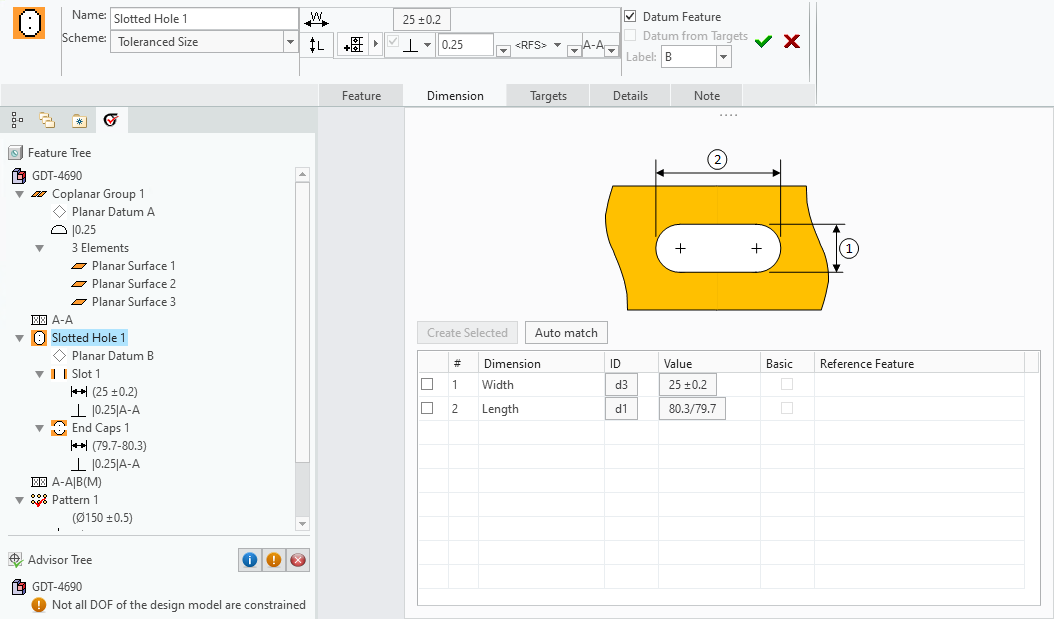
Dimension Slide-out Panel

1. Scheme Combo Box — Provides the scheme options that are available for the feature.
2. Scheme Illustration — Shows a picture of the required dimensions for the selected scheme.
3. Create Selected Button — When you click this button, the selected dimensions are created in the CAD model and then selected for the feature.
4. Auto Match Button — When you click on this button, the application attempts to match all unmatched dimensions in the table with the appropriate dimension from the CAD model.
5. Dimension Table — A table of dimensions for the selected scheme.
6. 'Offset Type' Selector — For some feature types, there may be a 'No Offset' option available, in which case the size dimension is located at the reference feature.
7. Reference Feature Selector — A combo-box that lists all of the applicable reference features.
Features of size and planar surface features support multiple scheme options. For those features, you will see a 'Scheme' combo box on the dashboard that includes all of the available schemes for that feature. When you add a feature of size (e.g., hole, shaft, tapered hole, etc.), the application inspects that CAD model for the dimensions associated with the feature and automatically selects a scheme that matches those dimensions. Those dimensions are then shown in the dimension table. If dimensions matching a supported scheme cannot be found, the "Basic Size" scheme is selected - that scheme does not require any dimensions.
GD&T Advisor does not automatically create dimensions in the CAD model. All dimensions required for the GD&T Advisor feature must already exist in the CAD model. |
Dimension Table
The dimension table consists of the following columns:
Dimension: Shows the name of the GD&T Advisor dimension corresponding to the dimension shown in in the scheme illustration.
ID: Shows a button that is labeled with the ID of the CAD dimension that the GD&T Advisor dimension is associated with. If it is not associated with a CAD dimension, the button is labeled 'Pick'. When you click on this button, the 'Select' process is initiated and the candidate CAD dimensions are displayed for selection. The dimension can be any applicable independent parametric dimension, driving dimension AE, or driven dimension AE.
Value: Shows a button that is labeled with the value of the dimension. When you click on this button, the 'Edit Dimension' dialog window is displayed, allowing you to change the properties of the dimension, including the tolerance type, precision, and tolerance values. Editing these properties modifies the properties of the associated CAD dimension as well. If dimension is not associated with a CAD dimension, this button is labeled 'Unknown' and is disabled.
Basic: Shows a check box, where applicable, to indicate whether or not the dimension is basic. In some cases, two dimensions are paired together, as indicated by the background color of the table rows e.g., a diameter and an offset dimension for tapered shaft). For these dimension pairs, one must be a toleranced dimension while the other must be basic, so the basic check box may only be selected for one of the dimensions of the pair.
Reference Feature: Shows a combo box, where applicable, containing the candidate reference features for the dimension. Some dimensions (e.g., offset dimensions) require a reference to another feature. The features that are included in the combo box are only those features that precede this feature in the feature tree and meet the requirements for the dimension. If the combo box includes multiple features, you should select the desired reference for the dimension. If there are no features listed in the combo box, no candidate features were found. In that case, you should cancel out of the dashboard and first add the required reference features to the model before adding this feature.
Note that when you click in a row in the table, the associated dimension is highlighted in the CAD model.