GD&T Advisor Dashboard - Geometric Control Properties
Geometric Control Properties
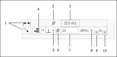
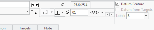
1. Stack Selectors — For some features, you can apply geometric tolerances to more than one element of the feature. For example, for a simple hole (pictured), you can apply geometric tolerances to the size dimension and directly to the feature surface. A separate annotation is created in the CAD model for each stack in which you have specified geometric controls.
2. Dimension Symbol — The dimension symbol (e.g., Ø or SØ) is defined automatically based on the dimension type.
3. Dimension Edit Button
◦ Clicking on this button launches the Dimension Edit window, enabling you to specify the dimension properties for the dimension.
4. Segment Control Tool
◦ The segment control tool provides the ability to add or remove segments to the feature control frame.
▪  – Add an independent segment.
– Add an independent segment.▪  – Add a composite segment.
– Add a composite segment.▪  – Remove segment.
– Remove segment.◦ The buttons for adding segments are automatically enabled or disabled to only allow you to add segments in conformance with selected tolerancing standard.
◦ The button to remove a segment is only available for the lower-most segment.
5. Geometric Characteristic Symbol Selector
◦ Clicking on this button displays a menu of geometric characteristic symbols that represent geometric controls that are applicable to the feature.
6. Tolerance Zone Modifying Symbol — The tolerance zone modifying symbol (e.g., Ø) is defined automatically based on the feature type and specified geometric tolerance.
7. Tolerance Zone Size Value — Specify the desired value for the tolerance zone size here.
8. Tolerance Zone Material Condition Modifier
◦ The tolerance zone material condition modifier is only displayed for applicable features of size.
◦ Clicking on this button displays a menu of applicable material condition modifiers.
◦ See Tolerance Zone Material Condition Modifiers (ASME), or Tolerance Zone Material Requirements (ISO) for more information.
9. Optional Modifiers
◦ Clicking on this button displays a menu of optional modifiers (e.g., projected zone, etc.)
10. Datum Reference Frame Selector
◦ Clicking on this button displays a menu of applicable datum reference frames (DRF) and the option to add a new DRF to the model
◦ See Datum Reference Frame Selector for more information.