Tutorial 3: Designing a Cooling Cavity Using a Body
In the tutorial, you design a cooling pipe cavity as a separate body.
• It is recommended that you work through the exercises sequentially during one Creo Parametric session. • In the exercises that follow you are instructed to use commands from the ribbon. After selecting items, you can also access these commands from the mini toolbar or by right-clicking. • In the videos of the exercises, to exit a tool a middle-click was used instead of  in many instances. in many instances. |
This tutorial is divided into 6 exercises to make it easier to follow:
• Exercise 1: Create a Cavity Body—Create a body that represents a cooling pipe cavity in the main body.
• Exercise 2: Create Cross Section Hatching—Create different cross section hatching for each body.
• Exercise 3: Create a Boolean Subtract Feature—Remove the material of the cavity from the main body.
• Exercise 4: Edit the Section—Edit properties of the section to see the effect on bodies.
• Exercise 5: Calculate Mass Properties—Calculate mass properties of the bodies in the part.
• Exercise 6: Create Layer States—Create separate layer states to represent the cavity, the main body without the cavity geometry, and both bodies.
Exercise 1: Create a Cavity Body
Watch a video that demonstrates the steps in this exercise:
1. Set the working directory to tutorial3 and open mb_negative_geom_demo1.prt
2. Click  and clear the (Select All) check box to turn off datum display in the graphics window.
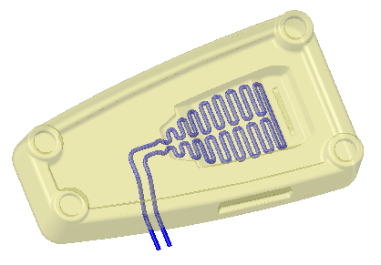
and clear the (Select All) check box to turn off datum display in the graphics window.3. Select PIPE_CURVE_BACKUP_FROZEN in the Model Tree or graphics window as you see in the following picture.
4. Click  Sweep. The Sweep tab opens.
Sweep. The Sweep tab opens.5. Click  Sketch. The Sketch tab opens.
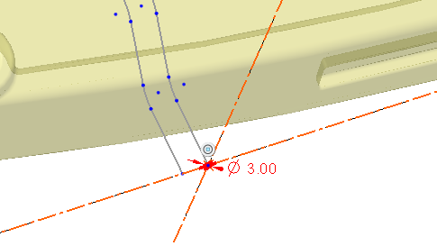
Sketch. The Sketch tab opens.6. Select  Circle. Click the right side of the sketch, and drag to create a circle.
Circle. Click the right side of the sketch, and drag to create a circle.7. Double-click the diameter dimension and type 3.0 and press ENTER.
8. Click . The Sweep tab opens.
. The Sweep tab opens.9. In the ribbon, click Body Options, or right-click, and then select the Create new body check box.
10. Click .
.11. Select the active body in the Model Tree, click again and type CAVITY as the name.
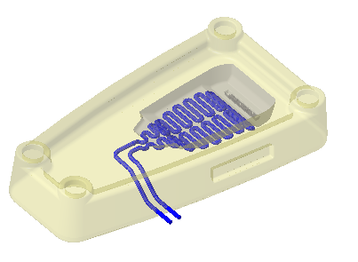
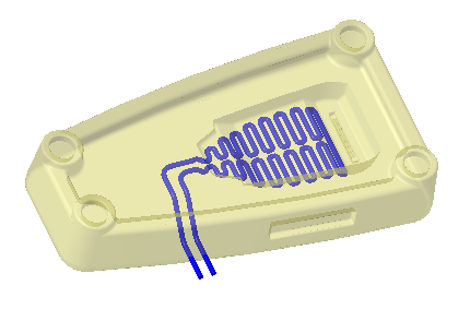
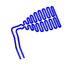
12. Select CAVITY and click View. Click the arrow below  Appearances and click the blue circle (ptc-metallic-blue).
Appearances and click the blue circle (ptc-metallic-blue).The appearance of body CAVITY changes to blue.
13. Click Model to return to the Model tab.
This concludes the first of 6 exercises.
Exercise 2: Create Cross Section Hatching
Watch a video that demonstrates the steps in this exercise:
1. In the Model Tree, select XSEC001, right-click and select  . The cross-hatching defined in the material shows on the model.
. The cross-hatching defined in the material shows on the model.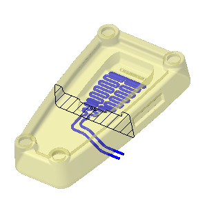
2. Right-click again, and select  . The Edit Hatching dialog box opens.
. The Edit Hatching dialog box opens.3. Select  Body in the Apply settings for list.
Body in the Apply settings for list.4. Select body MAIN and click  once. The space between the lines of hatching decreases with each click.
once. The space between the lines of hatching decreases with each click.5. Click Apply.
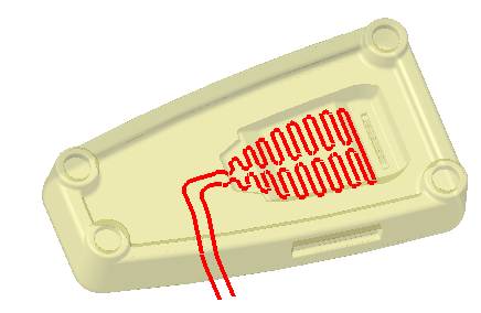
6. Select body CAVITY and click the arrow next to  .
.
.7. Select the second color in the first row as you see in the following picture:
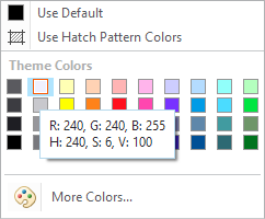
8. Click Apply.
9. Zoom in to the CAVITY body.
10. Under Hatch Pattern Characteristics, select the Angle box, type 90, and press ENTER.
11. Click . The space between the lines of hatching decreases with each click. You can click a number of times until you reach the density you want.
. The space between the lines of hatching decreases with each click. You can click a number of times until you reach the density you want.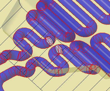
12. Click OK.
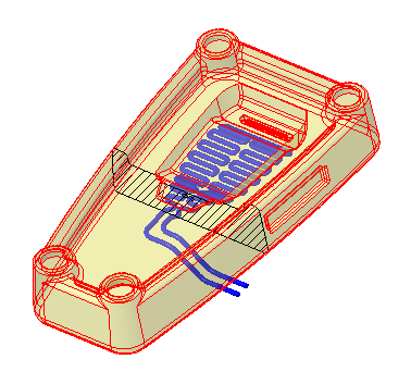
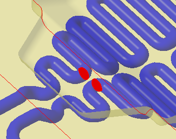
13. With the cross section selected, right click, and select the Show Interference check box.
14. Select the section in the Model Tree, right-click and perform the following operations:
◦ Select  to hide the cross section.
to hide the cross section.◦ Clear the Show Interference check box.
This concludes the second of 6 exercises.
Exercise 3: Create a Boolean Subtract Feature
Watch a video that demonstrates the steps in this exercise:
1. Click  Boolean Operations.
Boolean Operations.2. Click  Subtract.
Subtract.3. Select MAIN as the Body to modify.
4. Select CAVITY as the Modifying body.
5. Select  Keep bodies.
Keep bodies.6. Click .
.This concludes the third of 6 exercises.
Exercise 4: Edit the Section
Watch a video that demonstrates the steps in this exercise:
1. Right-click section XSEC001 in the Model Tree and select  . The Section tab opens.
. The Section tab opens.2. Move the arrow back and forth to see how the section view of the model changes.
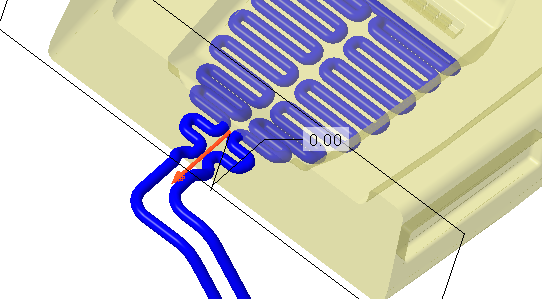
3. Click the Bodies tab and select Exclude selected bodies.
4. Select the CAVITY body to exclude.
5. Move the arrow again to see how the section view of the MAIN body changes.
6. Click Show Hatch Pattern.
Show Hatch Pattern.7. Make sure  Preview Capped Section is selected.
Preview Capped Section is selected.8. Click Bodies and select Include all bodies.
9. Drag the arrow to see capped ends display in the cooling pipe.
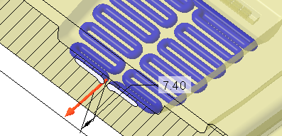
10. Click  .
.
.This concludes the fourth of 6 exercises.
Exercise 5: Calculate Mass Properties
Watch a video that demonstrates the steps in this exercise:
1. Click > . The Mass Properties dialog box opens.
2. Click Preview. The mass properties of the part appear in the preview window.
3. Scroll down to view the mass properties of the bodies in the part.
4. Click OK.
5. Select CAVITY in the Model Tree, right-click, and select Set as Construction.
6. Click > . The Mass Properties dialog box opens.
Construction bodies are not included in mass properties calculations. As there is only one body in the part considered in the calculations, no bodies appear in the preview. |
7. Click OK.
8. Click Model to return to the Model tab.
This concludes the fifth of 6 exercises.
Exercise 6: Create Layer States
Watch a video that demonstrates the steps in this exercise:
1. In the Graphics toolbar, click  . The View Manager dialog box opens.
. The View Manager dialog box opens.2. Click Layers.
3. Click New. Change the name to All and press ENTER.
4. Click New. Change the name to Cavity and press ENTER.
5. Select MAIN in the Model Tree, right-click, and select  .
.
.6. In the View Manager dialog box, right-click Cavity (+), and select Save.
7. Click OK.
8. Click New. Change the name to Main and press ENTER.
9. Select CAVITY in the Model Tree, right-click and select .
.10. In the View Manager dialog box, right-click Main (+), and select Save. The Save Display Elements dialog box opens.
11. Click OK.
12. Click Close to close the View Manager dialog box.
There are now 3 layer states in the Layers tab of the View Manager:
• All displays both the MAIN body and the CAVITY body.
• Cavity displays the CAVITY body.
• Main displays the MAIN body.
This concludes tutorial 3.