Tutorial 1: Creating a Multibody Part
In this tutorial, you learn how to create a part with multiple bodies and merge the bodies into one body.
• It is recommended that you work through the exercises sequentially during one Creo Parametric session. • In the exercises that follow you are instructed to use commands from the ribbon. After selecting items, you can also access these commands from the mini toolbar or by right-clicking. • In the videos of the exercises, to exit a tool a middle-click was used instead of  in many instances. in many instances. |
This tutorial is divided into 8 exercises to make it easier to follow:
• Exercise 1: Add Geometry to the First Body—Create the first feature of a part as a new body.
• Exercise 2: Create a Second Body—Create a new body when you add a feature to your part.
• Exercise 3: Display Contributing Features—Choose the body attributes and features to display in the Model Tree.
• Exercise 4: Create Rounds—Create rounds on one body and rounds on multiple bodies.
• Exercise 5: Shell the First Body—Create a new feature on an existing body.
• Exercise 6: Merge Bodies—Use Boolean operations to merge bodies into another body in the part.
• Exercise 7: Create a New Body—Create a new body when you add a feature to your part.
• Exercise 8: Change the Reference of a Body to a Different Body—Edit the references of a body feature to reference a different body.
Exercise 1: Add Geometry to the First Body
Watch a video that demonstrates the steps in this exercise:
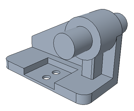
1. Set the working directory to tutorial1 and open mb_basics_demo1.prt.
2. Click  and clear the (Select All) check box to turn off datum display in the graphics window.
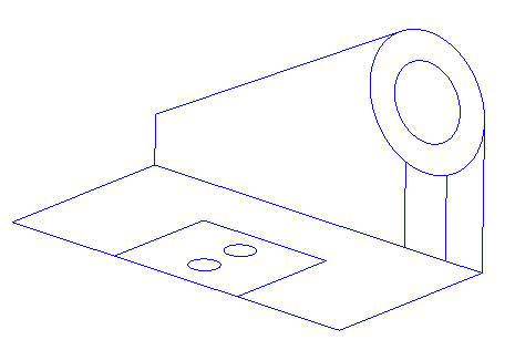
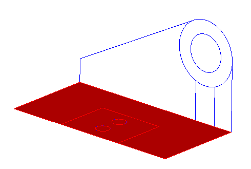
and clear the (Select All) check box to turn off datum display in the graphics window.3. Set the selection filter to Sketch Region.
4. Select the sketches at the bottom as you see in the following picture:
5. Click  Extrude and extrude the sketch downwards with a value for Depth of 3.5.
Extrude and extrude the sketch downwards with a value for Depth of 3.5.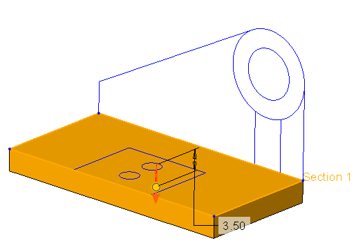
Click the arrow to change the direction of the extrude. |
6. Click .
.7. Select the 2 circles in the middle of the sketch and click Extrude.
Extrude.8. Make sure  Remove Material is selected and extrude the sketch downwards with the depth set to
  Through All.
Remove Material is selected and extrude the sketch downwards with the depth set to Through All.9. Click .
.10. Select the box at the bottom of the sketch and click Extrude.
Extrude.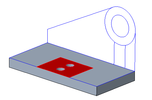
11. Extrude the sketch downwards with a value for Depth of 2.5. Make sure that the arrows are pointing down and inward as you see in the picture that follows.
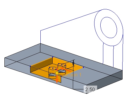
12. Click Body Options. Note that we are still creating geometry in Body 1. In the Model Tree Bodies folder, there is only one body.
13. Click .
.This concludes the first of 8 exercises.
Exercise 2: Create a Second Body
Watch a video that demonstrates the steps in this exercise:
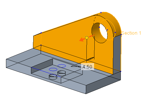
1. Select the perpendicular sketches without the inner circle, as you see in the following picture, and click Extrude.
Extrude.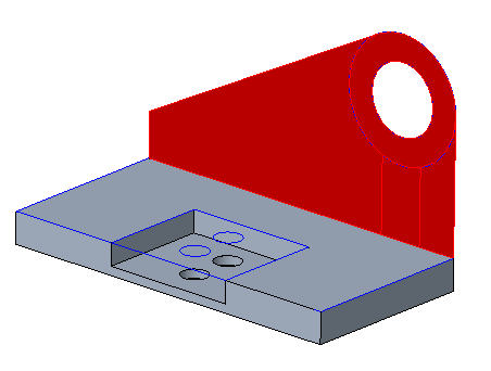
2. Extrude the sketch with a value for Depth of 4.5.
3. In the ribbon, click Body Options, or right-click, and then select the Create new body check box.
Unless you specify a different body or create a new body, geometry is created in the default body. |
4. Click . A new body (Body 2) is added as the default body to the Model Tree Bodies folder,
. A new body (Body 2) is added as the default body to the Model Tree Bodies folder,5. Select Body 2.
6. Click View.
7. Click the arrow below  Appearances and click the yellow circle (ptc-painted-yellow).
Appearances and click the yellow circle (ptc-painted-yellow).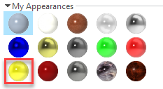
The appearance of Body 2 changes to yellow. Appearance assigned to a body overrides the appearance assigned to the part. A surface appearance can be applied to individual surfaces and overrides the color assigned to the body and the part.

8. Click Model to return to the Model tab.
9. Select the outside circle of the perpendicular sketch and click Extrude.
Extrude.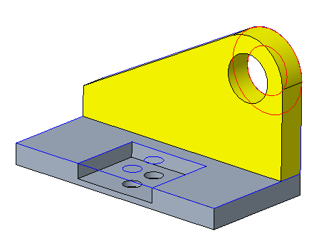
10. Set the direction of the sketch inward and make sure Remove Material is not selected.
Remove Material is not selected.11. Set the value for Depth to 13.5.
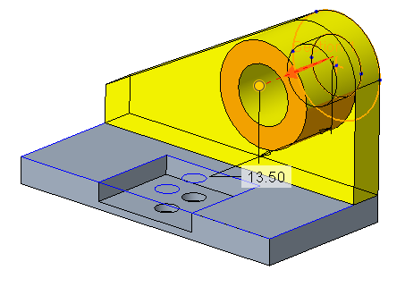
12. Click .
.13. Select the sketch under the extruded circle and click Extrude.
Extrude.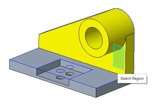
14. Set the value for Depth to 10 and click . The extrude is added to the default body, Body 2.
. The extrude is added to the default body, Body 2.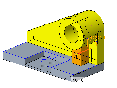
15. Click .
.This concludes the second of 8 exercises.
Exercise 3: Display Contributing Features
You can control the types of bodies, body material, and features contributing to the body that appear in the Model Tree. By default, all features created in a part are included in the Model Tree. You can also display these features in the node of the body to which they contribute.
1. Click  >
>  Tree Filters. The Model Tree Items dialog box opens.
> Tree Filters. The Model Tree Items dialog box opens.2. Click Body. Check boxes related to bodies appear.
3. Select the Contributing features check box.
4. Click OK.
5. Click the arrow next to a Body in the Model Tree to see which features contribute geometry to this body.
This concludes the third of 8 exercises.
Exercise 4: Create Rounds
The Round feature does not have a Body Options tab as a body reference is not required for this feature. You can create rounds on different bodies in a single round feature.
Watch a video that demonstrates the steps in this exercise:
1. In the Model Tree select Sketch 1 and Sketch 2, right-click and select  Hide.
Hide.
Hide.2. Set the selection filter to Geometry.
3. Click the arrow next to  , and select
  Shading With Edges.
, and select Shading With Edges.4. Select the outside edges of the support and click  Round.
Round.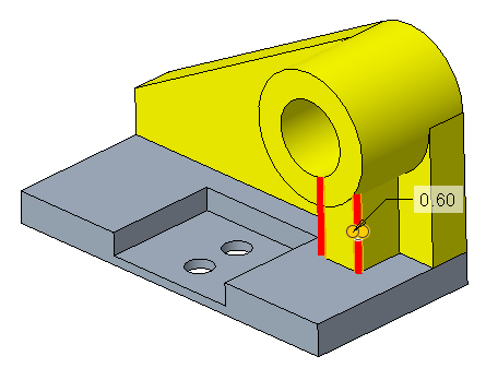
5. Set the radius to 0.6.
6. Click .
.7. Select the outside edges of the base and set the radius to 3.4.
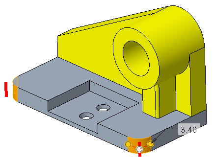
8. Click .
.9. Select the following edges, from both bodies, and create rounds with 1.00 radius.
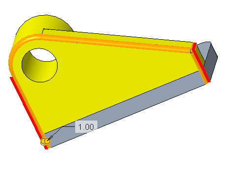
In the Model Tree, the feature Round 3 appears in both bodies.
10. Click .
.This concludes the fourth of 8 exercises.
Exercise 5: Shell the First Body
1. Select the bottom surface of the first body.
2. Click  Shell.
Shell.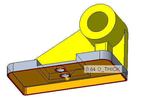
3. Accept the 0.64 default thickness.
4. Click .
.This concludes the fifth of 8 exercises.
Exercise 6: Merge Bodies
Watch a video that demonstrates the steps in this exercise:
1. On the Model tab, click  Boolean Operations. The Boolean Operations tab opens.
Boolean Operations. The Boolean Operations tab opens.2. By default,  Merge is selected.
Merge is selected.3. The Body to modify collector is active. Select Body 1.
4. The Modifying bodies collector becomes active. Select Body 2.
5. Click . The geometry of Body 2 is merged into Body 1 and it inherits the appearance of Body 1. Body 2 appears in the Model Tree as a consumed body with the  identifier, when you display consumed bodies in the Model Tree. The Body Merge feature appears in both bodies.
. The geometry of Body 2 is merged into Body 1 and it inherits the appearance of Body 1. Body 2 appears in the Model Tree as a consumed body with the identifier, when you display consumed bodies in the Model Tree. The Body Merge feature appears in both bodies.
This concludes the sixth of 8 exercises.
Exercise 7: Create a New Body
Watch a video that demonstrates the steps in this exercise:
1. Change the selection filter to Sketch Region.
2. Select Sketch 2, right-click and select  .
.
.3. Select the inner circle of the sketch.
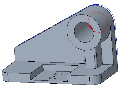
4. Extrude in both directions. In the first direction set the value of Depth to 8.0 and in the second direction set the value to 22.0.
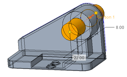
5. In the ribbon, click Body Options, or right-click, and then select the Create new body check box.
6. Click .
.7. Select Body 3 and click View. Click the arrow below Appearances and click the blue circle (ptc-metallic-blue).
Appearances and click the blue circle (ptc-metallic-blue).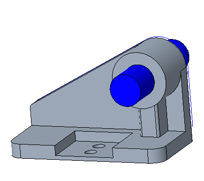
This concludes the seventh of 8 exercises.
Exercise 8: Change the Reference of a Body to a Different Body
Watch a video that demonstrates the steps in this exercise:
1. Right-click the extrude in Body 3 and select  . The Edit References dialog box opens.
. The Edit References dialog box opens.2. Select Body 3 from the list of Original references.
3. Select Body 1 as the new reference. A reference from Body 1 appears in the New reference box.
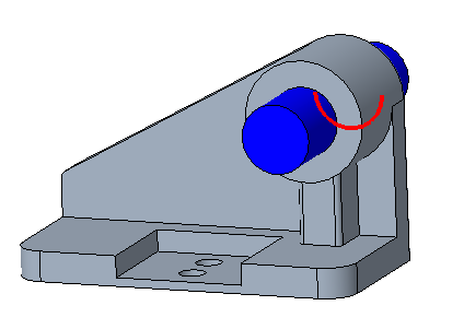
4. Click Preview to view the result in the graphics window.
5. Click OK. The extrude that was in Body 3 is now part of Body 1. Body 3 appears in the Model Tree as a body with no contributing features with the  identifier.
This concludes tutorial 1.