Adding A Fan Curve
In some applications, you add a fan curve when you do not want to model the actual fan geometry or if the geometry is complex. Creo Flow Analysis allows you to add the fan curves as a condition for an interface using the Expression Editor.
To add the fan curve, follow the steps below:
1. Select the interface to provide the fan curve.
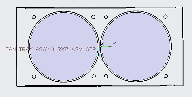
2. Under  Boundary Conditions > , select the two interfaces BOSS-EXTRUDE1_1_ and BOSS-EXTRUDE1_2_
Boundary Conditions > , select the two interfaces BOSS-EXTRUDE1_1_ and BOSS-EXTRUDE1_2_3. In the Properties panel, Model tab, for Flow, select the model.
4. Enter the values for Flow Direction.
5. Add the Pressure vs Flow data in table format and place the file in the working folder.
6. Click  Expression Editor.
Expression Editor.7. In the Local Expressions box, add the table file name.
8. For Q-DP Curve enter dp Pa
9. Click OK to close the Expression Editor.
The corresponding file for the table must be available in the working folder. To learn how to add pressure vs flow curve in table format, refer to Functions. |