Getting Started with Creo Flow Analysis
Introduction to CFA
Creo Flow Analysis (CFA) is a computational fluid dynamics tool used to easily simulate fluid flow. This helps predict the performance of a system or product involving internal or external fluid flow and heat transfer. The product analysis is enhanced and there is a validation and design optimization process without the need for extensive experience in computational fluid dynamics.
With Creo Flow Analysis you can combine simulation and design with minimum effort and without extensive experience in CFD. The outputs from the simulation are used to study the performance of the system in detail and help in modifying the design. The advantages of Creo Flow Analysis are listed below:
• Easier fluid volume extraction and automated meshing
• CAD-CFD associativity helps you to perform parametric simulations easily
• Comprehensive handling of complex geometries, wide range of complex physics such as turbulence and conjugate heat transfer
• Faster simulation performance
Workflow and Tutorials for Creo Flow Analysis
To guide you through the Creo Flow Analysis process, workflow topics and tutorials are provided:
• Workflow in CFA—Describes the CFA workflow of Preprocessing, Performing the simulation and Post-processing.
• Tutorials—Provide step-by-step instructions for the power inverter with and without heat transfer, cyclone separator, and fuel tank.
Starting a CFA Project
For introduction to the interface of Creo Flow Analysis see Interface for Creo Flow Analysis. To start a project, follow the steps listed below:
1. Open an assembly file in Creo Parametric.
2. Click >  Flow Analysis. The Flow Analysis tab opens.
Flow Analysis. The Flow Analysis tab opens.3. Click  New Project. The Flow Analysis Tree tab appears in line with the Model Tree tab.
New Project. The Flow Analysis Tree tab appears in line with the Model Tree tab.File Types in CFA
The file types handled by Creo Flow Analysis in the project working folder are described below:
• Project File (filename.spro)—Stores the operating conditions and grid file reference. The Project File is automatically stored when you click  Save Project. You can edit the project file using the Creo Flow Analysisinterface, a text editor, or script.
Save Project. You can edit the project file using the Creo Flow Analysisinterface, a text editor, or script.• Grid File (filename.sgrd)—Stores the grid data for a project. The grid file is automatically stored when the project file is stored, if the grid has been modified.
In a text editor, you can find the grid file using the Creo Flow Analysis interface. In a text editor, you can find the grid file associated with a given project in the project file. A Grid File with the same name as the Project File is generated by modifying a geometric entity such as the name of a Volume and saving it using Save or  Save As.
Save or Save As.• Multiple project files can share the grid file. • Compatible grid and project file are the only files needed to start or recreate a simulation. |
• Results File (Steady State results filename.sres and Transient results filename_xxxx.sres)— Creo Flow Analysis data files that contain the Transient or Steady State results for a given project. These contain the values of all the primary variables. In transient solutions, the “xxxx” corresponds to the time step associated with the simulation time and contains the data associated with that time step. Results data may be output in other formats using Additional Output Files.
Output File (filename.out)—Records the iteration or convergence history.
• Integrated Quantities (filename_integrals.txt)—Stores the values of the integrated quantities activated for output in each module:

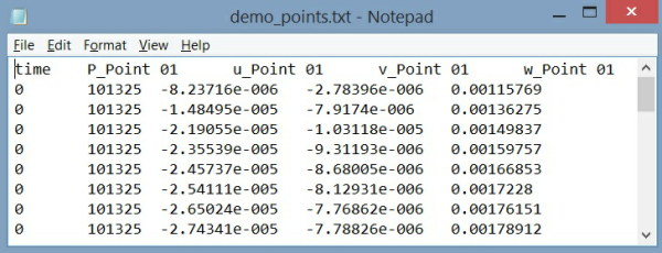
• Point Data (filename_points.txt)—Stores the values activated for output at the monitoring points.
• EnSight Format—Activates the output of data files compatible with the EnSight® post processing software. For Transient simulations, the Result Saving Frequency control the EnSight output.
• For Steady State Simulation, EnSight output is filename_ensight.case and filename_geo_ensight.data. • For Transient simulations, EnSight output is filename_geo_1_xxxx_ensight.data, filename_sca_1_xxxx_ensight.data, filename_sca_2_xxxx_ensight.data, filename_vec_1_xxxx_ensight.data, where xxxx is the time step. |