Common NC Sequence Parameters
The parameters that are common to all NC sequences are listed below. They are listed under a heading corresponding to the name of the branch when you set up the parameters. Follow the links under Related Links to access the topics describing the NC sequence-specific parameters.
|
|
• You must supply a value for all parameters that have a default of –1 (this means that the default value is not set by the system).
• Some parameters may have a value of dash (-), that is, "ignore". This means that the parameter will not be used. Usually a system default or another parameter will be used instead. The dash (-) value is only acceptable for those parameters that have it as a default.
• Length units for NC sequence parameters (where applicable) are the same as the units of the workpiece. If you change the workpiece units using the Same Size option (so that the dimension values are changed), the system also scales all the appropriate parameters of the currently existing NC sequences.
|
Search by category
• Names
Names
|
MACH_NAME
|
|
|
The machine name as required in post-processing. The default MACH_NAME is TURN for turning, MILL for all other NC sequences.
|
|
|
MACH_ID
|
|
|
The machine ID as required in post-processing. The default MACH_ID is 01.
|
|
|
NCL_FILE
|
|
|
The default name of the CL file for the NC sequence. The default is a dash (-), in which case the system generates a default name.
|
|
|
PRE_MACHINING_FILE
|
|
|
Enter the name of the file that you want included at the beginning of the CL file. The file must be located in your current working directory and have the extension .ncl. The default is a dash (-), that is, none.
|
|
|
POST_MACHINING_FILE
|
|
|
Enter the name of the file that you want included at the end of the CL file. The file must be located in your current working directory and have the extension .ncl. The default is a dash (-), that is, none.
|
Cut Depth and Allowances
|
TOLERANCE
|
|
|
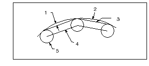
The tool path approximates curved geometry by moving in small straight line increments, as shown in the following drawing. The maximum distance that the straight line path deviates from the curved geometry is set by TOLERANCE. The default TOLERANCE is 0.001" (0.025 mm).  1. TOLERANCE 2. Design Surface 3. Machined Surface 4. Tool Centerline path 5. Tool |
|
|
MAX_DISCRETIZ_STEP
|
|
|
Specifies the maximum permissible distance between two points in the tool path. This parameter is available for ball endmill, radius endmill, and flat endmill tools in Surface milling (Isolines, Projected Cuts), Cut Line milling, Conventional milling, Profile milling, Finishing, and Volume milling (only profile).
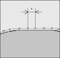
If the distance between two points in the tool path is more than MAX_DISCRETIZ_STEP, Creo NC creates intermediate points such that the distance between two points is always lesser than MAX_DISCRETIZ_STEP. The intermediate points are within the tolerance value and are degouged.
If no value is specified for MAX_DISCRETIZ_STEP (default), only the tolerance value is used to generate the tool path points.  1. MAX_DISCRETIZ_STEP |
|
|
MIN_DISCRETIZ_STEP
|
|
|
Specifies the minimum permissible distance between two points in the tool path. There is no default. When setting this value, make it greater than the tolerance value.
|
|
|
POINT_DISTRIBUTION
|
|
|
Defines the way points are distributed along the tool path. The options are:
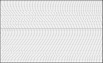
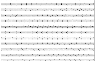
• ALIGNED (default)—The points in a slice of the tool path are aligned with those of the preceding and succeeding slices.  • SHIFTED—The points in a slice of the tool path do not form a line with those of the preceding and succeeding slices.  This parameter is available for ball endmill, radius endmill, and flat endmill tools in Surface milling (Isolines, Projected Cuts), Cut Line milling, Conventional milling, Profile milling, Finishing, and Volume milling (only profile). |
Feeds and Speeds
|
CUT_FEED
|
|
|
The feed rate used for cutting motion. The default CUT_FEED is not set (displayed as "–1").
|
|
|
CUT_UNITS
|
|
|
IPM (inches per minute—default), FPM (feet per minute), MMPM (millimeters per minute), FPR (feet per revolution), IPR (inches per revolution), MMPR (millimeters per revolution).
|
|
|
RETRACT_FEED
|
|
|
The rate at which the tool moves away from the workpiece. The default RETRACT_FEED is a dash (-), in which case the CUT_FEED will be used.
|
|
|
RETRACT_UNITS
|
|
|
IPM (default), FPM, MMPM, FPR, IPR, MMPR.
|
|
|
FREE_FEED
|
|
|
The feed rate used for rapid traverse (RETRACT_UNITS are used for rapid feed rate units). The default FREE_FEED is a dash (-), in which case the RAPID command will be output to the CL file. The same happens if FREE_FEED is set to 0.
|
|
|
PLUNGE_FEED
|
|
|
The rate at which the tool approaches and plunges into the workpiece (in Milling and Turning). The default PLUNGE_FEED is a dash (-), in which case the CUT_FEED will be used.
|
|
|
PLUNGE_UNITS
|
|
|
IPM (default), FPM, MMPM, FPR, IPR, MMPR.
|
Machine Settings
|
LINTOL
|
|||
|
Allows you to specify the linear tolerance interpolation used by post-processor, for multi-axis milling and Mill/Turn rotary linearization. Outputs the "LINTOL / r" statement at the beginning of the CL file. The default LINTOL is a dash (-), in which case the LINTOL statement will not be output.
|
|||
|
CIRC_INTERPOLATION
|
|||
|
Specifies the format in which the tool motion along an arc or circle will be output to the CL file. The options are:
• POINTS_ONLY—Use this format for machines that have no circular interpolation capabilities. Arcs are approximated by a series of straight line moves affected by tolerance (as shown in the illustration above).
• ARC_ONLY (default)—Use this format for machines that have full circular interpolation. Only the CIRCLE statement and the minimum number of points necessary for post-processing will be output to the CL file. The number of points is defined by the NUMBER_OF_ARC_PTS parameter.
• POINTS_&_ARC—The CIRCLE statement and the maximum number of points according to the tolerance value will be output to the CL file.
• APT_FORMAT—Use it if your post-processor expects the circular motions to be in the APT format.
|
|||
|
OUTPUT_3DNURBS
|
|||
|
If set to YES, Creo NC creates NURBS interpolation output instead of linear or circular interpolation output for all feed rate moves including the entry and exit motions. The tool path is also smoothened to keep C2 continuity wherever possible and minimize curvature changes. The default value is NO.
NURBS interpolation is supported in Surface Milling (3-axis and 5-axis), Finishing, Trajectory Milling, Swarf Milling, Profile Milling, Volume Milling, Roughing, Reroughing, Local Milling, Face Milling, Pocket Milling, and Corner Finishing.
|
|||
|
NUMBER_OF_ARC_PTS
|
|||
|
Specifies the number of points to be output to the CL file if CIRC_INTERPOLATION is set to ARC_ONLY. The default is 3.
|
|||
|
COOLANT_OPTION
|
|||
|
ON, OFF (default), FLOOD, MIST, TAP, THRU.
|
|||
|
COOLANT_PRESSURE
|
|||
|
NONE (default), LOW, MEDIUM, HIGH.
|
|||
|
COORDINATE_OUTPUT
|
|||
|
Specifies which coordinate system, MACHINE_CSYS or SEQUENCE_CSYS, is used as the CL data origin (the default is MACHINE_CSYS).
|
|||
|
FIXT_OFFSET_REG
|
|||
|
Allows you to specify the fixture transformation offset register used on your machine. The default FIXT_OFFSET_REG is a dash (-), that is, none. If you specify another value ("n") for FIXT_OFFSET_REG, the "SET\ /\ OFSETL, n" and "SET / OFSETL, OFF" statements will be output.
|
|||
|
END_STOP_CONDITION
|
|||
|
Specifies the stop command to be issued at the end of the CL data output for an NC sequence:
• NONE (default)—No command.
• OPSTOP—The OPSTOP command will be issued.
• PROGRAM_STOP—The STOP command will be issued.
• GOHOME—The GOHOME command will be issued. If you specify a Home point for the operation, the tool appears in the Home location. If you do not specify the Home point, the system outputs the GOHOME command anyway, but it does not move the tool, and issues a warning.
|
|||
|
GO_HOME_REGISTER
|
|||
|
Allows you to specify the GOHOME register used on the machine. In case of machine with multiple GOHOME positions, this unique register allows you to specify a specific GOHOME position for a spindle. To see the output in the CL file, the value of END_STOP_CONDITION parameter must be GOHOME. The output in the CL file is GOHOME / [integer value].
|
|||
Entry/Exit Motions
|
START_MOTION
|
|
|
Defines how the tool will move from the Start point of the NC sequence to the beginning of the cut motion. If you do not specify the Start point (using the Start option in the SEQ SETUP menu), this parameter will be ignored. The values are:
• DIRECT (default)—The approach motion will be a straight line from the Start point of the NC sequence to the start of the cut.
• Z_FIRST—The tool will first move in the direction parallel to the z-axis of the NC Sequence coordinate system, then move in the direction normal to the z-axis and start cutting.
• Z_LAST—The tool will first move in the direction normal to the z-axis of the NC Sequence coordinate system, then move along the z-axis and start cutting.
Not applicable for Wire EDM.
|
|
|
END_MOTION
|
|
|
Defines how the tool will move from the end of the cut to the End point of the NC sequence. If you do not specify the End point (using the End command in the SEQ SETUP menu), this parameter will be ignored. The values are:
• DIRECT (default)—The exit motion will be a straight line from the end of the cut to the End point of the NC sequence.
• Z_FIRST—The tool will first move in the direction parallel to the z-axis of the NC Sequence coordinate system until it reaches the Z coordinate of the End point, then move to the End point in the direction normal to the z-axis.
• Z_LAST—The tool will first move in the direction normal to the z-axis until it reaches the XY coordinates of the End point, then move to the End point along the z-axis.
• X_Only—The tool will move only in the direction of the x-axis.
• Z_Only—The tool will move only in the direction of the z-axis.
Not applicable for Wire EDM.
|