HMX Table Customization
The customization of tables has been enhanced in V50, residing predominantly within the HMX Tables panel. The HMX Tables panel enables you to create custom Wire List, Cavity Table and BOM tables. An HMX Advanced license is required to make use of the HMX Table Customization functionality. If you don't create any custom tables, HMX will revert to the creation of the default tables. Created custom tables are saved to a file named tables.hmx. This file resides in your Creo Parametric working directory. Previously created tables are read from this file and populate in the user interface. Furthermore, HMX will parse this file to create the custom tables during processing. This file should not be edited under any circumstances.The Tables panel and its key sections are displayed below.
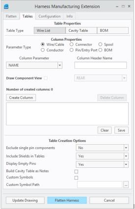
Table Properties
The Table Properties section determines which table will be customized during the flattening process. All tables previously generated by HMX (that is the Wire List, BOM, and the Cavity Table) can be modified to a your specification. If a table customization already exist for this table in the working directory, then a visual representation of the table appears in the table preview window.
Column Properties
The Column Properties section contains the majority of customization capabilities within HMX. You can determine which parameter type you wish to add to this table and then can select from six primary areas Wire/Cable, Conductor, Connector, Pin/Entry Port, Spool, or BOM. Once selected, a set of parameters will be made available to use from the Column Parameter dropdown menu. Use the Column Parameter function to select a column to add to the customized table. The column parameters are retrieved from the information held in the current model.
The Column Header Name text field is used to provide a custom name for each column parameter selected. This property is mandatory to complete the table customization process.
Cavity Table Customizations
Within the table customization options, Table Creation Option Customization is not available for customization of Cavity Tables.
Cavity Table Properties Customizations
The checkbox Draw Component View is only selectable after you select the Cavity Table from the table type option, wherewhere cavity view can be selected and generated. The available view orientations are FRONT, REAR, TOP, or ALL. An example of the output is shown in the figure below.
The figure below shows cavity tables where a user selects the ALL option and all three orientations are presented.
Cavity Table Creation Option Customizations
This functionality can be used on both customized tables and on default tables generated by HMX. The three functions are:
• Building Tables as Notes
• Customizing Symbols in Cavity Views
• Excluding single pin components
Build Cavity Tables as Notes
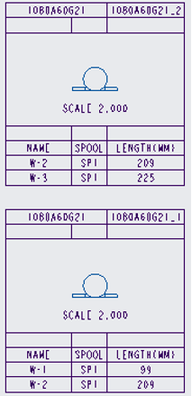
The Build Cavity Tables as Notes functionality enables you to display tables as a series of notes. An example of the Build Cavity Tables as Notes functionality is shown in the figure below.
To use this functionality, a symbol or view is required to display cavity tables as notes.
To enable cavity tables as notes in the current session of HMX, proceed with the following:
1. Start up HMX.
2. Go to the Tables tab.
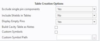
3. Under Table Creation Options, select the Build Cavity Tables as Notes check box.
4. Click Flatten Harness or close HMX.
In both cases, this option will be saved in the HMX configuration file for future sessions.
To change the option, repeat the steps shown above but uncheck the tables as notes option. HMX will save the users configuration on a session-by-session basis.
Include Shields in Tables
The option Include Shields in Tables controls the output of conductors of type shield in the Wire List and Cavity Table.
If the option Include Shields in Tables is set to Yes, any shields which are fully routed and complete will appear in the generated tables, if the user has the correct license.
The default value for this option is No, indicating that no shield type conductors will appear in the tables.
Custom Symbols in Cavity Tables
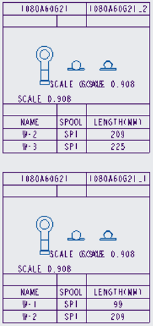
The custom symbol in the cavity table replaces the view generated by HMX with a user-defined symbol. No other functionality is affected by using custom symbols. A user can define a custom cavity table, build cavity tables as notes, or use the default tables available in HMX. The figure below shows custom symbols in a cavity table.
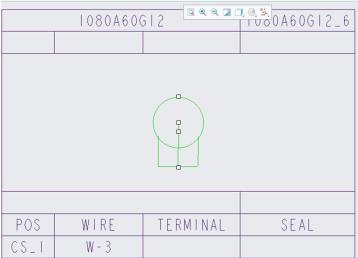
Symbols must be created within Creo Parametric and must be of the symbol definition file type (.sym).
Files of any other file type will be ignored.
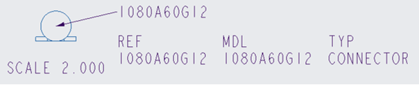
When creating symbols for models, ensure that symbols comply with the following naming convention: <Part name in Creo>.sym
For example, in the above cavity table, the custom symbol was named 1080A60G12.sym.
When using custom symbols you can use these methods for retrieving the symbols in HMX.
• Store the symbols to be used in the pre-existing HMX symbol directory. This is held in the interconnect_app folder of your Creo Parametric installation directory. The location of this folder is <Creo Parametric install folder>\Common Files\interconnect_app\symbols.
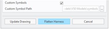
• Create a folder directory on the machine and set the path to the directory in the tables panel as shown in the figure below.
To initiate using the custom symbols as notes functionality:
1. Start up HMX
2. Go to the Tables Tab
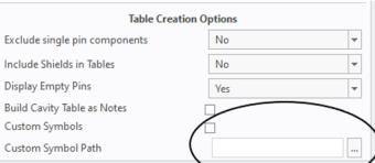
3. In the Table Creation Options select theCustom Symbols check box
The custom symbol functionality is not retained in the next session, and it requires configuration during each use of HMX.
Exclude Single Pin Components
In the Table Creation Options, Exclude single pin components can be set to Yes to prevent the creation of cavity tables for single pin, single entry-port connectors. Any connectors with multiple pins or multiple entry ports will still have cavity tables created.
Bill of Materials Table Customization
The following figure shows the selection of the BOM Table type.
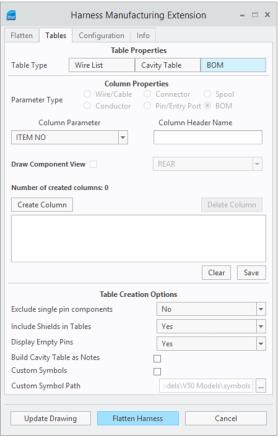
After selecting the BOM option, the allowed parameters types are limited. This is the expected functionality. Only the content of the Bill of Materials can appear in a BOM table.
Constraints
Consider the following constraints for the table customization:
• The maximum number of columns allowed per table is 50. HMX does not support more than 50 columns.
• The maximum width for an individual column is 81 characters.
• A minimum of two columns are required to draw cavity views in a cavity table.
• Wire List and Cavity tables cannot contain Bill of Materials information with customization.
• Bill of Materials tables cannot have Wire/Cable, Conductor, Connector, Pin/Entry Port, or Spool information with customization.
• Only parameters that exist in Creo can be represented in the model.
• Parameters must be derived from the model or electrical parameters.
• Cavity Tables are the only type of table able to have a component view.