Retaining Drawing Changes
A big part of the new functionality included in HMX V50 is the ability to retain a drawing object changes.
These changes include the following:
• Positional information for views, tables, reference notes, and balloons
• Size (width) information for Wire List and Cavity Tables
• Segment orientation changes within a 2D sketch
• Creating bend in segments in a 2D sketch
• Constraints applied to attached components
• Broken views
This information is stored directly in the drawing, when the drawing is saved, and no external files are required.
The workflow for this functionality is as follows:
1. Run HMX to create your drawing. This can be either a fully default drawing, or it can have any number of custom tables.
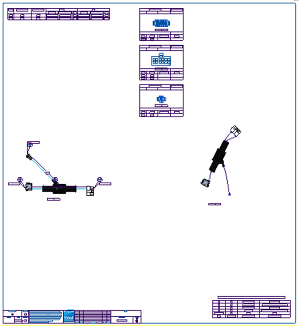
2. Move tables, views, notes and symbols as required.
3. (Optional) Open the asksmt.asm assembly and change the orientation of the segments, or create bends in existing segments, and then Close the Sketcher and the assembly window.
4. Save the drawing.
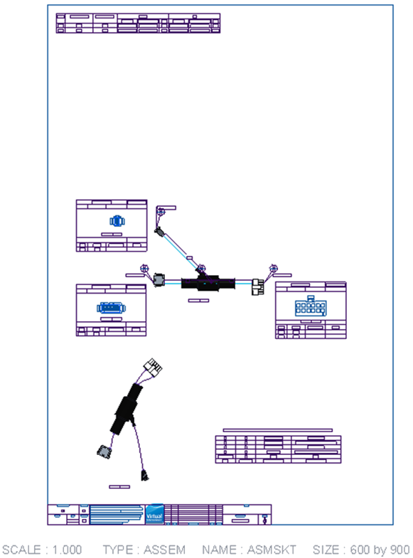
5. At a later date, in a fresh session, open your original assembly, and then bring the saved drawing into session.
6. Close the drawing, without erasing it from the session.
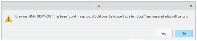
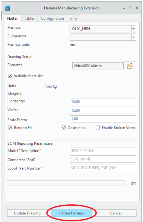
7. Start HMX, and select Yes to reuse the drawing as a template .
8. (Optional) Change configuration options or table customizations.
9. Click the Flatten Harness button.
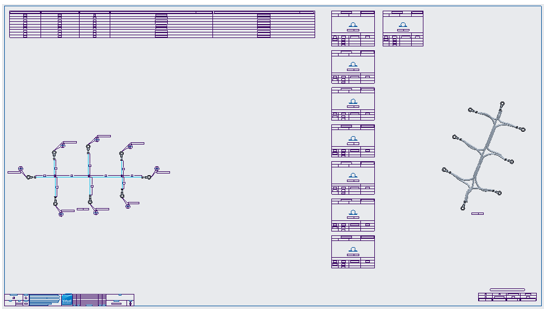
10. A new drawing is generated, which combines the old positioning of the drawing objects with the new changes to tables, views, notes, and symbols generation.
Only the Save operation is supported, Save As is not supported because it creates a copy of the drawing. |
Positional Changes
Positional changes refer to the location of objects on the drawing sheet. You can move the Wire List, Cavity and Bill of Materials tables anywhere on the sheet, and their position will be retained when the drawing is reused as a template via the reuse-drawing-as-template functionality.
These positions can be absolute, in the case of the Wire List and BOM tables, 2D and 3D views, or referencing another object, in the case of cavity tables and views, reference designators and balloons referencing the connector they belong to.
Absolute positioning places the object at the same sheet location on the second run, as on the first saved run.
Referencing positions are used for the cavity tables and views. If these are moved from their default location to adjacent to a connector to allow minor changes in the routing of the 3D to persist in the 2D sketch, while also removing overlaps between the cavity table and the 2D sketch.
Table Content Changes
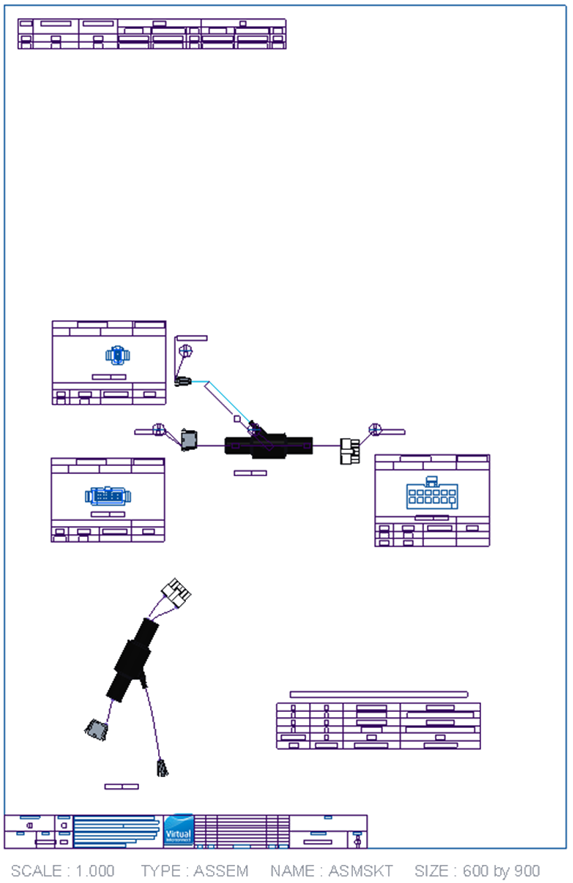
Table content changes refer to the table customizations that are applied on the second run of a retained drawing. When the table content changes, HMX tries to accommodate the new changes into the retained positioning of a drawing object elements to remove any overlaps that may occur. As a result, the following changes can occur in the following order:
1. When the Wire List table is customized to have either fewer or more columns, any objects to the right of it are moved further right.
2. The cavity table and cavity view positions are reused, offset from their connector references, while also maintaining the distance between the cavity tables that have not t been moved, further pushing any objects on the right to further right.
3. The 3D view is placed at its retained absolute positioning.
4. The BOM table is placed at its retained absolute positioning.
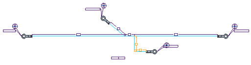
Sketch Segment Changes
Supported sketch segments fall into two categories:
• Rotating a segment or segment chain
• Breaking and creating a bend in a segment
Original 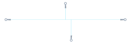 | Bent/Rotated 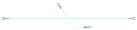 |
When either of these changes is performed to a 2D sketch, after returning to the HMX-created drawing, you will notice that the dimensioning for the sketch has exploded. To resolve this, the Update Drawing command has been added to HMX user interface. Selecting this button when there is a drawing active in the Creo Parametric window will reset to default the dimensions, notes and symbols on the 2D view.
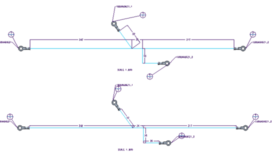
If you reuse the saved drawing that contains sketch modifications to create a new drawing, any broken and bent segments appear with an orange dimension to indicate that a change was made to that segment.
Constraint Retention
Following the creation of an HMX drawing, you can edit the constraints applied to a component. To retain the modifications when the saved drawing is used as a template, you must adhere to the following constraint retention rules.
Consider these rules listed in the order of importance:-
1. For new constraints applied to the parts in the ASMSKT.ASM, the assembly reference must be an explicit feature that HMX has created with a name from the model tree.
2. For axial placed components, the newly applied constraints must not cause the component to violate the geometry placement rules that HMX expects.
3. The component must be fully constrained to preserve the saved output.
4. Any constraint type can be used.
When can retained drawing edits not to be applied
In certain cases, the changes you made to a drawing cannot be retained if the configuration options have significantly changed between the runs. These cases are as follows:
• Changing between variable and non-variable sheet size
• Changing the Bend to Fit option
• Changing Cosmetics inclusion
• Changing from a customized table without a view to a custom table with a view or to a default table
• Changing the connector dimensioning scheme
• Changing the option of Include Shields in Tables
• Changing the option to including all pins in the Cavity tables
• Changing the Cone Angle value
• Changing the Exclude single pin components option
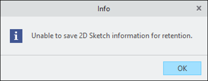
Additionally, if disjointed segments are created during the sketching editing, you receive a warning that your saved changes are not valid and cannot be reused to create another drawing.
If any of these situations have occurred, when the drawing is used as a template you receive a warning that your retained changes may not be reapplied and that a default drawing may be created.