Example: Running a Fatigue Study in Creo Ansys Simulation
This example illustrates the end-to-end workflow of setting up and running a fatigue analysis and viewing and analyzing the results.
In this example there is a pulley system which consists of a shaft made of FE 40 material and a pulley made of steel. The pulley is mounted on the shaft with 4 bolts. A belt passes around the pulley. The force applied by the belt is modeled as a bearing load with a value of 5000 N.
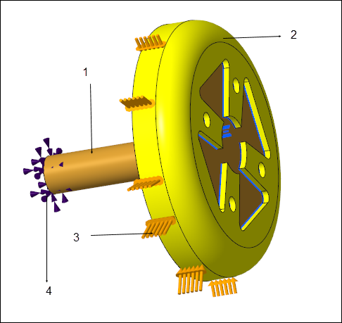
1. Shaft made of FE 40 material
2. Pulley made of steel
3. Force exerted by belt on the pulley modeled as a bearing load with value 5000 N
4. Fixed constraint that holds the end of the shaft in place
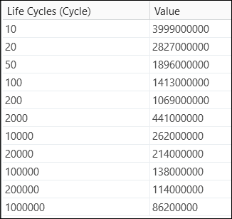
The pulley rotates at a high rpm and so has to withstand high cycle fatigue. To evaluate the fatigue life of the pulley because of the load exerted on it by the belt the fatigue material properties are defined for the pulley material. The cyclic stress properties for the steel material are defined. The stress life curve is defined for the pulley material (steel) as a table function with values as shown below:
Fatigue behavior is defined for the model with the following parameters:
• Analysis type—Stress life
• Component—Von Mises stress
• Loading Type—Fully reversed
• Design Life—1.0e06 cyles
The following are the different results obtained when the study is run:
Result | Contour Plot of Result | Interpretation |
|---|---|---|
Biaxial Indication |  | Since the biaxial indication varies between -1 (pure shear) and 0.99 (almost 1) it implies pure biaxial loading in some areas. |
Equivalent Alternating Stress | 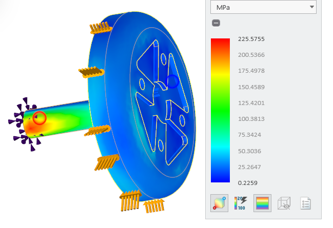 | A low value of EAS here implies a higher life. |
Fatigue Damage | 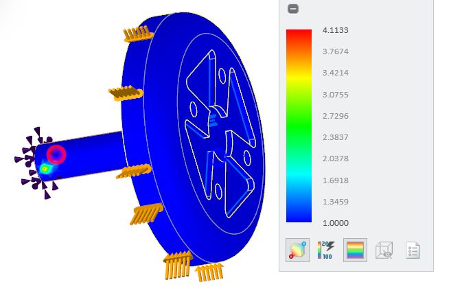 | In this case the fatigue damage is 1.0 for the pulley which implies the part is safe for design life. |
Fatigue Life |  | For the pulley the fatigue life is 1e06 which is equal to the design life. |
Safety Factor |  | The maximum safety factor for the pulley is around 10 which implies it is safe. |