To Create HSM Undercut Machining Sequences
Define a 3-axis Undercut machining sequence to remove material from the undercut areas.
Ensure that the active operation references a Mill or Mill/Turn work center.
|
|
The  HSM Undercut Machining command with the Mill/Turn work center is available when you have both the Complete Machining and ModuleWorks-based Mold Machining licenses. HSM Undercut Machining command with the Mill/Turn work center is available when you have both the Complete Machining and ModuleWorks-based Mold Machining licenses. |
1. Click Milland then click HSM Undercut Machining in the High Speed Milling group. The HSM Undercut Machining tab opens.
HSM Undercut Machining in the High Speed Milling group. The HSM Undercut Machining tab opens.2. Click  Tool Manager or select
  Edit Tools from the Tool list to open the Tools Setup dialog box and add a new cutting tool or change tool parameters. The tool list only includes tools that are valid for the step.
Tool Manager or select Edit Tools from the Tool list to open the Tools Setup dialog box and add a new cutting tool or change tool parameters. The tool list only includes tools that are valid for the step.To show tools for the current step and the active head on the machine tool, set the INCLUDE_ALL_TOOLS_IN_LIST option to YES. |
The supported tools for this sequence are as follows:
◦ Side Milling (default)
◦ Key Cutter
◦ Advanced Side Milling
Alternatively, right-click in the graphics window and select Tools.
3. To preview the cutting tool and its orientation in the graphics window, click  Tool Preview next to the Tool list.
Tool Preview next to the Tool list.The Tool Preview button becomes available after you select a tool. |
Alternatively, right-click the graphics window and select the Tool Preview option on the shortcut menu. After you select a tool, the Tool Preview option is available on the shortcut menu of the graphics window.
To exit the tool preview, right-click the graphics window and select Cancel tool preview from the shortcut menu or click Tool Preview again.
Tool Preview again.4. To change the coordinate system that defines the orientation of the step, click the collector adjacent to  and select a coordinate system. If the operation coordinate system differs from the step coordinate system, right-click the collector for the following commands:
and select a coordinate system. If the operation coordinate system differs from the step coordinate system, right-click the collector for the following commands:◦ Default—Replaces the selected coordinate system with the default reference. The default is the orientation that is copied from the previous step or from the operation.
◦ Information—Displays the information of the selected coordinate system.
If your work center setup has two spindles, choose Main Spindle or Sub Spindle from the list, and select a coordinate system each for the main and sub spindle.
The sub spindle is available when you have both the Complete Machining and ModuleWorks-based Mold Machining licenses. After you specify a coordinate system for an NC sequence, it remains in effect until you change it. |
Alternatively, right-click the graphics window and select Orientation from the shortcut menu.
5. Define the options in the following tabs:
◦ Undercut
◦ Links
◦ Options
◦ Process
6. Click  to open a separate CL Data window.
to open a separate CL Data window.7. Click  to get a dynamic preview of the toolpath in the graphics window.
to get a dynamic preview of the toolpath in the graphics window.8. After you define the mandatory step elements, select a command for toolpath validation:
◦ To play the toolpath, click the arrow next to  and select .
and select .◦ To recompute the toolpath, click the arrow next to and select  .
.
and select .◦ To perform gouge checking against surfaces of the reference part, click the arrow next to and select  .
.
and select .◦ To view the simulation of material removal as the tool is cutting the workpiece, click the arrow next to and select  . The Material Removal tab with integrated simulation environment opens.
and select . The Material Removal tab with integrated simulation environment opens.9. Select one of the following options to complete the sequence:
◦ Click  to save the changes.
to save the changes.◦ Click  to pause the process and use one of the asynchronous tools or click
  to resume.
to pause the process and use one of the asynchronous tools or click to resume.◦ Click  to cancel the changes.
to cancel the changes.References Tab
Select the machining references and optionally define the containment loops.
Define the following options:
• Reference model—Select a reference part which consists of a single body or multiple bodies, or select a body of a reference part for the undercut machining.
Alternatively, right-click the graphics window and select Reference Model from the shortcut menu.
• Containment Loops—Select individual closed loops in the collector or click Details and select chains of loops. The areas inside the loops are machined. Alternatively, right-click the graphics window and select Containment Loops from the shortcut menu.
Click  to flip the containment area for inverting the machining side. is available only for a 3D containment loop.
to flip the containment area for inverting the machining side. is available only for a 3D containment loop.Parameters Tab
Specify the required manufacturing parameters. You can also click  to copy parameters from an earlier step or click
  to edit parameters specific to the Undercut machining sequence. By default, the required parameters for the selected tool are defined by relations that you can modify from the Relations dialog box.
to copy parameters from an earlier step or click to edit parameters specific to the Undercut machining sequence. By default, the required parameters for the selected tool are defined by relations that you can modify from the Relations dialog box.Alternatively, right-click the graphics window and select Parameters from the shortcut menu.
For more information on the parameters specific to the Undercut machining sequence, see Undercut Machining Sequence Parameters.
Clearance Tab
Optionally define the retract and the start and end points on the toolpath.
• Retract—Specify the following:
◦ Type (default type is Plane)
◦ Reference
◦ Value
• Start and End Points—Specify the Start point and End point for the toolpath.
Alternatively, right-click the graphics window and select Start Point and End Point from the shortcut menu to select start and end points of the toolpath.
Undercut Tab
Select the following options:
• Machine only undercuts—Select the checkbox to machine only the undercut areas. This checkbox is selected by default.
If you clear this checkbox, all visible and non-visible surfaces in the reference part are machined.
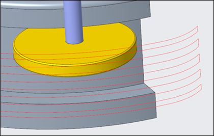
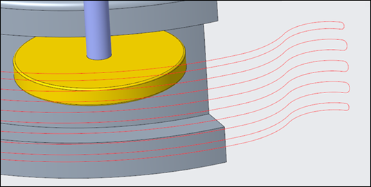
• Connect segmented toolpaths—Select the checkbox to link all segmented toolpath moves.
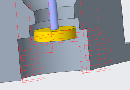
For example, when the Connect segmented toolpaths checkbox is cleared:
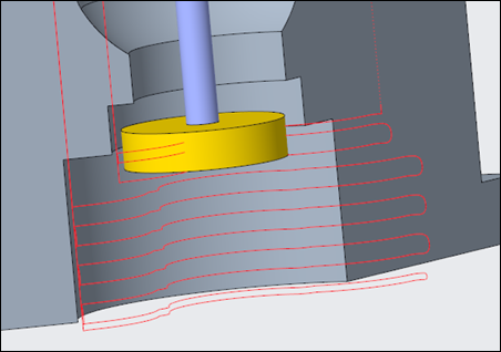
For example, when the Connect segmented toolpaths checkbox is selected:
Clearing the Connect segmented toolpaths checkbox prevents air cuts during undercut machining. |
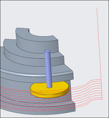
• Undercut radial clearance—Enter the radial clearance for the safe tool approach and retract when machining the undercut areas.
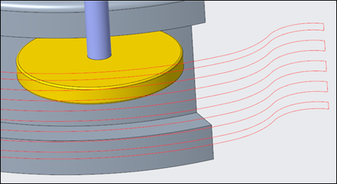
For example, when the Undercut radial clearance value is set to 0:
For example, when the Undercut radial clearance value is set to greater than 0:
• Adaptive step depth—Select this checkbox to create adaptive step depth slices during undercuts machining. The additional toolpath slices are generated in the shallow areas. After you select this checkbox, the following parameters become available:
◦ Minimum step depth—Determines the minimum distance between two adjacent passes in the specified machining direction.
◦ Maximum step over—Defines the maximum distance between the two neighboring cuts measured in XY plane.
Adaptive slices are added when the distance between the two consecutive constant step depth slices in the XY plane is larger than the Maximum step over value. The slices are added till the maximum step over slice becomes similar or equal to the next conjugative slice.
Adaptive slices are not generated in the following cases:
◦ The Minimum step depth value is greater than the half of the constant step depth value. For example, if the Minimum step depth value is 2.0 MM and the STEP_DEPTH value is 1.0 MM, adaptive slices are not generated.
◦ The Maximum step over value is greater than the distance between the two consecutive constant depth slices measured in the XY plane.
The following image illustrates how the adaptive slices are added in the shallow areas:
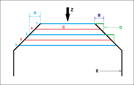
1. Constant step depth slices
2. Constant step depth slices
3. Constant step depth slices
4. Adaptive step depth slices
5. Adaptive step depth slices
A—Distance between two consecutive constant step depth slices in XY plane
B—Maximum step over in XY plane
C—Adaptive step depth slices
D—Projection of maximum step over slice in Z direction
E—Undercut surface area
Case 1: When the Maximum step over value in XY plane (B) is less than the distance between the two consecutive constant step depth slices (A), the adaptive depth slices are added at the middle of the two consecutive constant step depth slices.
Case 2: When the Maximum step over value in XY plane (B) is greater than the distance between the two consecutive constant step depth slices (A), the adaptive depth slices are not generated.
Case 3: When the Maximum step over value in XY plane (B) is equal to the distance between the two consecutive constant step depth slices (A), the adaptive depth slices are not generated.
Case 4: When the Maximum step over value in XY plane (B) is less than the distance between the two consecutive constant step depth slices (A) and the Minimum step depth value is greater than the half of the STEP_DEPTH value, the adaptive depth slices are not generated.
If you select the Adaptive step depth checkbox, the flat surfaces in the undercut areas are not machined completely. To machine the flat undercut surfaces, use one of the following methods: • Set a finer tolerance value. • Clear the Adaptive step depth checkbox. • Specify a large step depth value if you want to machine only the flat undercut surfaces. |
Links Tab
Define the lead and link types
• Lead—Specify the following options:
◦ Lead-in and Lead-out—Select the entry and exit motions to and from the machining surfaces.
▪ None—Tool enters or exits without any lead in and out motion.

▪ Tangential arc (default)—Tool takes horizontal arc for steep areas and vertical arc for shallow areas while leading in and out.

▪ Horizontal tangential arc—Tool takes horizontal arc for all areas while leading in and out.
◦ Lead radius—Enter the arc radius for the entry and exit of the toolpath as a percentage of tool diameter (default) or absolute value. The default value is 25 percent.
• Links—Define the connection types between adjacent slices with the following options:
◦ Small links—Select one of the following:
▪ Direct—Creates the shortest connection in a straight line between the slices, without any retracting movements.
▪ Follow Surface—Creates a connection that follows the existing geometry between the slices without any retracting movements.
▪ Blend Spline (default)—Creates a connection in tangential arcs between the slices.
▪ Retract to Clear Distance—Creates a connection in straight line between the slices. The tool retracts to the specified clear distance.
▪ Retract to Retract Plane—Creates a connection in straight line between the slices. The tool retracts to the retract plane while connecting slices.
If the selected link type does not satisfy the safety conditions, next safe link type is used. |
◦ Small link threshold—Enter a threshold value for the SMALL_LINK parameter as a percentage of step depth (default) or absolute value. Links smaller than the threshold value are considered as small links. The default threshold value is 110 percent.
Options Tab
Open a part or assembly to use as a cutting tool adapter. Alternatively, click  to copy cutting tool adapter from another step.
to copy cutting tool adapter from another step.Tool Motions Tab
To create a Goto Point tool motion, select Goto Point. For more information, see To Create a Goto Point Tool Motion.
To insert a CL command along the toolpath, select CL Command. For more information, see To Insert a CL Command for Tool Motions.
The Tool Motions tab is visible only when you define machining references. |
Process Tab
Use any of the following options for the machining step:
• Calculated Time—Click  to automatically calculate the machining time for the step. The Calculated Time box shows the time.
to automatically calculate the machining time for the step. The Calculated Time box shows the time.• Actual Time—Specify the machining time.
Properties Tab
Specify the name or comments for the step.
• Name—Displays the name of the step. You can type another name.
• Comments—Type the comments associated with the step in the text box or use the following options:
◦  —Read in an existing text file containing step comments and replace any current step comments.
—Read in an existing text file containing step comments and replace any current step comments.◦  —Insert the contents of an existing text file of step comments at the cursor location. Preserve any current step comments
—Insert the contents of an existing text file of step comments at the cursor location. Preserve any current step comments◦  —Save current step comments in a text file.
—Save current step comments in a text file.◦  —Accept the current step comments.
—Accept the current step comments.