Workflow to Logically Designate Components and Route Cables
The workflow for designating the components and routing cables using logical information is as follows:
1. Import the logical data. For more information, see Importing Logical Data.
2. Auto Designate the connectors using logical data. Click  Cabling Data
 .
.
Cabling Data.3. Route wires and cables using logical data. Use the Route Cables dialog box to route the selected wires or cables between their from and to connectors. The wires automatically follow the shortest path through the network.
Example
Refer the cabling_assembly.asm sample assembly to learn how to logically designate components and auto route cables through them. Sample models are available here. Open cabling_assembly.asm. Select LOGICAL_ROUTE from the  Saved Orientations list. Set LOGICAL_ROUTING as the working harness.
Saved Orientations list. Set LOGICAL_ROUTING as the working harness.1. Click Cabling Data > . The File Open dialog box opens.
Cabling Data > . The File Open dialog box opens.2. Set Type to XML Wire List, and select shield.xml to import the logical data. In the Layers Import dialog box, select all layers and click OK.
3. Set the Harness Context to CABLING_ASSEMBLY.ASM.
4. Click .
.5. Click LOGICAL-1 and click the component as shown in the figure.

6. In the Entry Ports table for LOGICAL-1, set 09ZR-8M-P to TRUE in the Designated Entry Port column.
7. Click LOGICAL-2 and click the component shown in the figure.
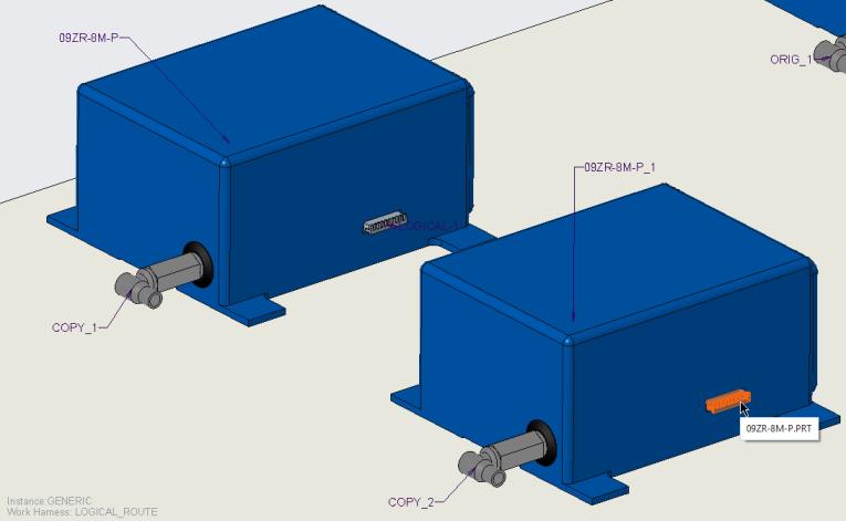
8. Set 09ZR-8M-P to TRUE, and click OK.
9. Click  Route Cables to open the Route Cables dialog box.
Route Cables to open the Route Cables dialog box.10. Click  . The Find Cables dialog box opens.
. The Find Cables dialog box opens.11. Click W-999, click  to move it to the items selected list, and click OK.
to move it to the items selected list, and click OK.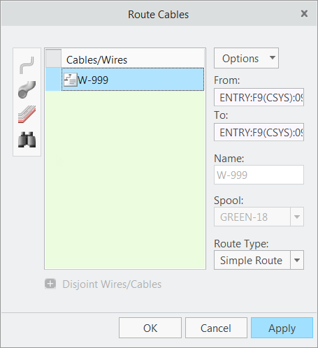
Note the from, to, spool, and route type information is filled from the logical data.
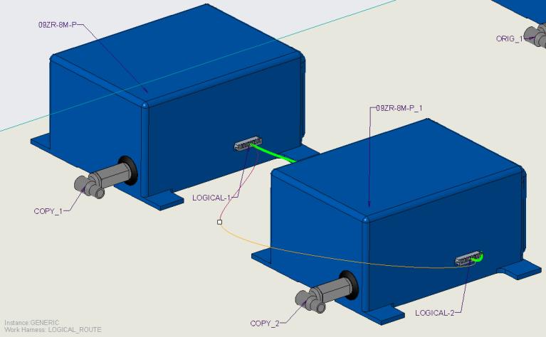
12. Click Apply. The wire is routed between the selected connectors.

13. Click Cancel to close the Route Cables dialog box.
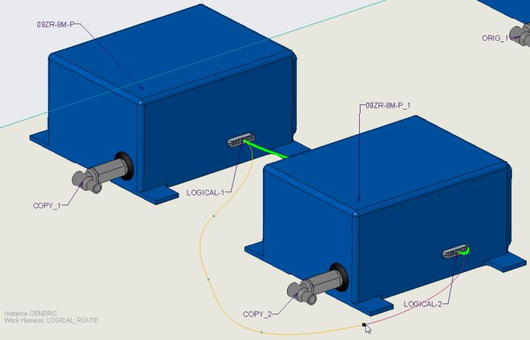
14. Click Location. The Location tab opens.
15. Add locations as shown in the figure.
Click  to flip the direction of progression along the selected segment. to flip the direction of progression along the selected segment. |
To Undesignate a Connector
1. Right click the connector and select  Undesignate.
Undesignate.2. The component is no longer designated as a connector.