To Create Geodesic 5 Axis Finish Sequences
Define Geodesic 5 axis finish sequences to machine complex 3D components with a toolpath having a constant step-over and undercuts area.
Ensure that the active operation references a 5 axis Mill or Mill/Turn work center that has milling capability.
|
|
The  Geodesic 5 Axis Finish command with the Mill/Turn work center is available when you have both the Complete Machining and ModuleWorks-based Mold Machining licenses. Geodesic 5 Axis Finish command with the Mill/Turn work center is available when you have both the Complete Machining and ModuleWorks-based Mold Machining licenses. |
1. Click > Geodesic 5 Axis Finish in the High Speed Milling group. The Geodesic Finish tab opens.
Geodesic 5 Axis Finish in the High Speed Milling group. The Geodesic Finish tab opens.2. Click Tool Manager or select Edit Tools from the tool list box to open the Tools Setup dialog box and add a new cutting tool or change tool parameters. The tool list only includes tools that are valid for the step.
To show tools for the current step and the active head on the machine tool, set the INCLUDE_ALL_TOOLS_IN_LIST option to YES. |
3. To preview the cutting tool and its orientation in the graphics window, click  Tool Preview to the right of the Tool list.
Tool Preview to the right of the Tool list.The Tool Preview button becomes available after you select a tool. |
Alternatively, right-click the graphics window and select the Tool Preview option on the shortcut menu. After you select a tool, the Tool Preview option is available on the shortcut menu of the graphics window.
To exit the tool preview, right-click the graphics window and select Cancel tool preview from the shortcut menu or click Tool Preview again.
Tool Preview again.4. To change the coordinate system that defines the orientation of the step, click the collector adjacent to  and select a coordinate system. If the operation coordinate system differs from the step coordinate system, right-click the collector for the following commands:
and select a coordinate system. If the operation coordinate system differs from the step coordinate system, right-click the collector for the following commands:◦ Default—Replaces the selected coordinate system with the default reference. The default is the orientation that is copied from the previous step or from the operation.
◦ Information—Displays the information of the selected coordinate system.
If your work center setup has two spindles, choose Main Spindle or Sub Spindle from the list, and select a coordinate system each for the main and sub spindle.
The sub spindle is available when you have both the Complete Machining and ModuleWorks-based Mold Machining licenses. After you specify a coordinate system for an NC sequence, it remains in effect until you change it. |
Alternatively, right-click the graphics window and select Orientation from the shortcut menu.
5. Define the options in the following tabs:
◦ Link
◦ Options
◦ Process
6. Click  to open a separate CL Data window.
to open a separate CL Data window.7. Click  to get a dynamic preview of the toolpath in the graphics window.
to get a dynamic preview of the toolpath in the graphics window.8. After you define the mandatory step elements, select a command for toolpath validation:
◦ To play the toolpath, click the arrow next to  and select .
and select .◦ To recompute the toolpath, click the arrow next to and select  .
.
and select .◦ To perform gouge checking against surfaces of the reference part, click the arrow next to and select  .
.
and select .◦ To view the simulation of material removal as the tool is cutting the workpiece, click the arrow next to and select  . The Material Removal tab with integrated simulation environment opens.
and select . The Material Removal tab with integrated simulation environment opens.9. Select one of the following options to complete the sequence:
◦ Click  to save the changes.
to save the changes.◦ Click  to pause the process and use one of the asynchronous tools or click
  to resume.
to pause the process and use one of the asynchronous tools or click to resume.◦ Click  to cancel the changes.
to cancel the changes.Reference Tab
Select the machining references. Optionally, define guide curves and containment curves.
• Under Machining References, set the following options:
◦ Selection type—Select surfaces or a previous step.
▪ Surface—Select individual surfaces or click Details and select surface sets from the graphics window. Right-click and select Remove to remove the surfaces.
Alternatively, right-click the graphics window. On the shortcut menu, select Machining Reference and then select the required surfaces from the model tree.
Disjoint surfaces are not supported. |
Click  to select the direction of the machining side. becomes available if you have selected quilt surfaces.
to select the direction of the machining side. becomes available if you have selected quilt surfaces.The toolpath calculation performance varies based on the total number of defined machining surfaces as the toolpath performs gouge checks and collision checks for all defined machining surfaces. For best performance, select only the required machining surfaces. |
▪ Previous Step—Use the surfaces from the previous defined sequence.
Alternatively, right-click the graphics window. On the shortcut menu, select Step and then select the required step from the model tree.
◦ Create toolpath on holes—Select this check box to create toolpath on filled hole surfaces. All boundaries, except for the outer boundary of the mesh, are considered as the boundaries of a hole. It is not possible to select the holes for filling and machining. All holes are considered for machining.
• Under Guide Curves, set the following options:
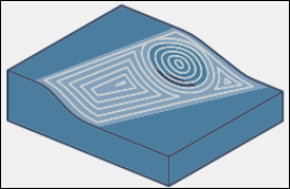
◦ Pattern Type—Select the pattern of the toolpath. Patterns can be open or closed.
▪ Parallel to multiple curves—The toolpath is generated with an offset from all guide curves at the same time.
1. First guide curve
2. Second guide curve
3. Third guide curve
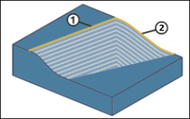
▪ Morph between two curves—The toolpath morphs from one guide curve to another guide curve. The containment must be around or inside the guide curves. Cuts outside the morph field do not maintain valid stepover.
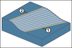
1. First guide curve
2. Second guide curve
Morph between two curves requires exactly two guide curves to generate a toolpath. For the Containment area input type, the toolpath algorithm automatically extracts curves. For User defined input type, you must provide two guide curves. |
Alternatively, right-click the graphics window. On the shortcut menu, select Pattern Type and then select the required option.
◦ Select the input type:
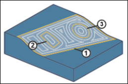
▪ Containment area—Extract the guide curves automatically from the containment curves or from the machining surfaces to generate the toolpath accordingly.
For defined containment curves, the outer shapes of these containment curves are considered as guide curves. If there are no defined containment curves, guide curves are based on the outer shape of the selected machining surface. |
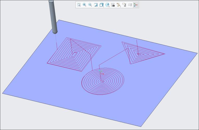
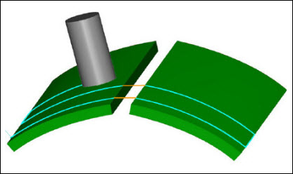
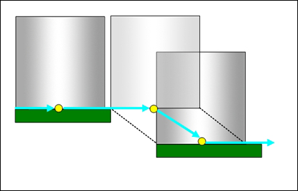
The following image shows the containment curves selected by three different shape curves for the Parallel to multiple curves pattern type option.
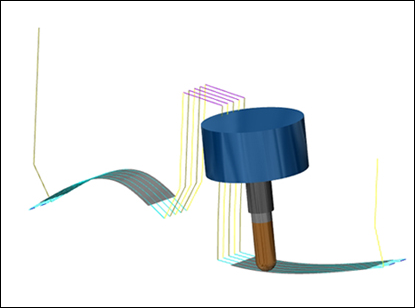
The following image shows the toolpath generated based on the containment area.
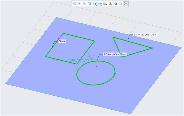
▪ User defined—Select the curves or edges manually to use them as guide curves. The generated toolpath is based on these guide curves.
After you define the machining surface, a collector is activated. You can select open or closed curves or a mix of these curves. You can also use the Details button to select the guide curves.
1. First guide curve selection
2. Second guide curve selection
Note that for morph pattern, if the selected curves are intersecting with each other, then they are joined and considered as one curve, and the toolpath is not generated. In such cases, do not select self-intersecting guide curves.
For example:
1. First intersecting guide curve
2. Second intersecting guide curve
Alternatively, right-click the graphics window. On the shortcut menu, select Input and then select Containment area or User defined.
When you select > on the shortcut menu, the Guide Curves command is selected by default. You can then proceed to select the required guide curves.
• Under Containment Curves, a collector is activated after you define the machining surface. You can select closed loops of curves or edges. Toolpath is contained in these closed loops. You can also use the Details button to select closed containment curves.
Alternatively, right-click the graphics window and select Containment Curves from the shortcut menu.
• Guide curves and containment curves must only be on the machining surface. • If you define all body surfaces as machining reference without a containment area and guide curves, the toolpath is not calculated and an error message appears. In such cases, you must define a containment area and guide curves. |
Parameters Tab
Specify the required manufacturing parameters. You can also click  to copy parameters from an earlier step or click
  to edit parameters specific to Geodesic 5 Axis finish. By default, the required parameters for the selected tool are defined by relations that you can modify from the Relations dialog box.
to copy parameters from an earlier step or click to edit parameters specific to Geodesic 5 Axis finish. By default, the required parameters for the selected tool are defined by relations that you can modify from the Relations dialog box.Alternatively, right-click the graphics window and select Parameters from the shortcut menu.
Clearance Tab
Define the retract and the start and end points on the step toolpath.
• Retract—Define the values for the retract.
◦ Type
▪ Plane
▪ Cylinder
▪ Sphere
◦ Reference
◦ Orientation
◦ Value
• Start and End Points—Specify the Start Point and End Point for the step toolpath.
Axis Control Tab
Define the tool tilt options.
• Titling Strategy—Select how the tool tilts.
◦ Relative to cutting direction (default)—Unless there is a collision, this option keeps the tool normal to the machining surface. When GOUGE_AVOID_OPTION is set to TILT, the tool tilts automatically up to 90 degrees on encountering a collision.
Set the following options:
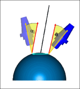
▪ Tilt angle—Specify an angle in which the tool can be tilted from the surface normal. The angle range is -179.99 to 179.99.

▪ Lead angle—Specify an angle to limit the tool axis orientation along a lead move. The angle range is -89.99 to 89.99.
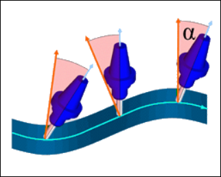
▪ Maximum tool tilt angle—Specify the maximum angle in which the tool can be tilted from the reference axis. The angle range is 0 to 180.
◦ Tilted with fixed angle to axis—Unless there is a collision, this option keeps the tool parallel to the reference axis. When GOUGE_AVOID_OPTION is set to TILT, the tool tilts automatically up to 90 degrees on encountering a collision.
Set the following options:
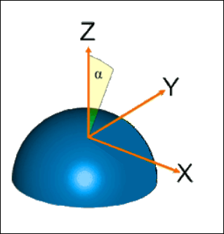
▪ Reference axis—Select Z axis or Custom axis.
Z axis is the default selection. It is the same z axis of the step orientation.
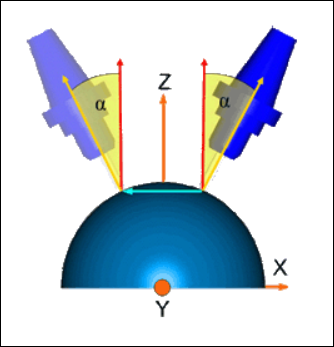
For Custom axis, select an axis around which the tool tilts.
▪ Tilt angle—Specify the angle in which the tool can be tilted from the reference axis towards the surface normal direction with a specific angle. The angle range is -179.99 to 179.99.
▪ Rotary angle—Specify the angle that is based on the tilt angle. The engagement along cutting direction is automatically increased. The angle range is -180.00 to 180.00.
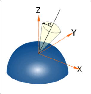
▪ Maximum tool tilt angle—Specify the maximum angle in which the tool can be tilted from the reference axis. The angle range is 0 to 180.
Link Tab
Define the link type, tool approaches, and retracts.
• Under Lead, specify Lead-in (entry) and Lead-out (exit) motions to and from the machining surfaces.
Specify the arc radius as a percentage of tool diameter or absolute value in the Lead Radius option. The default arc radius is 25% of the tool diameter.
To flip the lead radius to the opposite side, click .
.The following lead-in and lead-out types are available:
◦ Automatic arc (default)—Consists of two splines. The first spline leaves the surface tangential to the surface normal direction, similar to a tangential arc. The second spline uses the tool axis tilting orientation to connect tangentially to the plunge or retract motion.
The toolpath considers the most suitable lead-in and lead-out motions according to the machining surface.
The arc radius may vary to a lower value than you specified in the Lead Radius option. |
◦ Vertical tangential arc—Connects with the toolpath start point tangential to the contour. The orientation is orthogonal to the tool plane.
◦ Horizontal tangential arc—Connects with the toolpath start point tangential to the contour. The orientation is on the machining plane.
◦ Tangent arc—Connects with the toolpath start point tangential to the contour. The orientation is the tool plane.
Tool side tilting influences the lead orientation. |
For lead types other than Automatic arc, the lead-in and lead-out motions are not created if there is tool collision. In such cases, you can flip the side of the lead-in and lead-out motions to avoid collision or change the type of Lead-in and Lead-out.
• Under Gaps Along Cut, define the connection type using the Small gaps and Large gaps option. Gaps along the cut are caused by the features of a machining surface shape and the toolpath type you select.
Specify the threshold for determining whether to use small gaps or large gaps in the Small gaps size option. You can specify the small gap size as a value or in percentage of the tool diameter. The default is 20% of the tool diameter.
You can select the following types of Small gaps and Large gaps:
◦ Blend Spline—Defines tangential arcs connection between the gap edges. The cut feed rate value is applied for this type.
By default, Blend Spline is selected for the Small gaps type.

◦ Direct—Shortest straight-line connection between the gap edges without any retracting movements. The cut feed rate value is applied for this type.
◦ Follow Surface—The connection follows existing geometry on the gap edges without any retracting movements. The cut feed rate value is applied for this type. This only works with the activated gouge checking strategy.
◦ Retract to clear distance—Straight line connection between the gap edges. The retracting tool uses the CLEAR_DIST parameter for entry and the PULLOUT_DIST parameter for exit. This gap contains retracting along tool axis to PULLOUT_DIST, connection, and approach along tool axis from CLEAR_DIST. Each segment has its own feed rate.
By default, Retract to clear distance is selected for the Large gaps type.
◦ Retract to rapid distance—Straight line connection between the gap edges. The retracting tool uses the RAPID_DISTANCE parameter. This gap contains retracting along tool axis to RAPID_DISTANCE, connection, and approach along tool axis segments. Each segment has its own feed rate.

◦ Retract to clearance—Straight line connection between the gap edges. The retracting tool uses retract defined in the Clearance tab. This gap contains retracting along tool axis to clearance area, connection, and approach along tool axis segments. Each segment has its own feed rate.
• Under Links Between Slices, define the connection type between adjacent cuts or cutting layers using the Small moves and Large moves option.
Specify the threshold for determining whether to use small moves or large moves in the Small moves size option. You can specify the small moves size as a value or in percentage of stepover. The default for the Small moves size option is 150% of stepover.
The following types of Small moves and Large moves are available:
◦ Blend Spline (default for Small moves)
◦ Direct
◦ Follow Surface
◦ Retract to clear distance (default for Large moves)
◦ Retract to rapid distance
◦ Retract to clearance
The toolpath behavior for the Small moves and Large moves type is similar to the toolpath behavior for Small gaps and Large gaps types. |
• Under Tangential Extensions, specify the following options:
◦ Start—Extend or trim at the start of the cut. Use a value or percentage of the tool diameter. Positive values extend the toolpath and negative values trim the toolpath.
◦ End—Extend or trim at the end of the cut. Use a value or percentage of the tool diameter. Positive values extend the toolpath and negative values trim the toolpath.
◦ Extend trim gaps—Select the check box to activate the trimming or extending of toolpath segments that are considered as gaps along the cut.
Check Surfaces Tab
Define the parts and surfaces to use as limits on the tool motions during machining.
• Add machining references—Select the check box to add machining reference as check surfaces for gouge-free toolpath. By default, the Add machining references check box is selected.
• Add reference parts—Select the check box to add reference part as a check surface for gouge-free toolpath.
• Check surfaces—Add surfaces, fixtures, or references that you want to degouge toolpath against in the Check surfaces collector.
• Check clearance—Specify the clearance for the selected check surfaces.
Default value is 0.
• Check clearance is not available if you select the Add machining references check box. • Check clearance is only available after you define the check surfaces. |
Alternatively, right-click the graphics window and select Check Surfaces.
• If no surfaces are selected as check surfaces, then the toolpath does not check for gouges or collisions. • If you clear the Add machining references check box and add reference part surfaces including machining surfaces as check surfaces, the toolpath considers the defined stock allowance on all machining surfaces. The toolpath applies the defined value of Check clearance on the remaining check surfaces. • The toolpath calculation performance varies based on the total number of defined check surfaces as the toolpath performs gouge checks and collision checks for all defined check surfaces. For best performance, select only the required check surfaces. |
Options Tab
Open a part or assembly to use as a cutting tool adapter. Alternatively, click  to copy cutting tool adapter from another step.
to copy cutting tool adapter from another step.Tool Motions Tab
To create a Goto Point tool motion, select Goto Point. For more information, see To Create a Goto Point Tool Motion.
To insert a CL command along the toolpath, select CL Command. For more information, see To Insert a CL Command for Tool Motions.
The Tool Motions tab is visible only when you define machining references. |
Process Tab
Use any of the following options for the machining step:
• Calculated Time—Click  to automatically calculate the machining time for the step. The Calculated Time box shows the time.
to automatically calculate the machining time for the step. The Calculated Time box shows the time.• Actual Time—Specify the machining time.
Properties Tab
Specify the name or comments for the step.
• Name—Displays the name of the step. You can type another name.
• Comments—Type the comments associated with the step in the text box or use the following options:
◦  —Read in an existing text file containing step comments and replace any current step comments.
—Read in an existing text file containing step comments and replace any current step comments.◦  —Insert the contents of an existing text file of step comments at the cursor location. Preserve any current step comments
—Insert the contents of an existing text file of step comments at the cursor location. Preserve any current step comments◦  —Save current step comments in a text file.
—Save current step comments in a text file.◦  —Accept the current step comments.
—Accept the current step comments.