Geodesic Parameters
CONTAINMENT_OFFSET
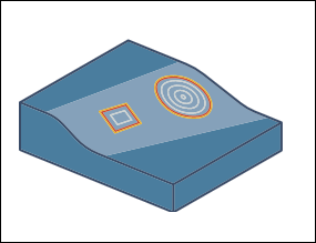
Creates a virtual offset of the containment curve at the given distance. The toolpath is generated up to this curve. Ensure that a surface mesh is available for generating such a toolpath.
For positive values, the cut is created outside the containment area.

For negative values, the cut is created inside the containment area.
For 0 value, there is no offset and the cut is created up to the boundaries of the containment area.
Default: 0
CUT_TYPE
Specify one of the following cut types:
• ONE_WAY—Moves the tool in one cutting direction. The direction is established by direction one or direction two.
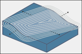
• ZIG_ZAG—Moves the tool in the opposite cutting direction with every new cut. The direction is established for the first cut only as direction one or direction two.
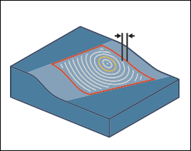
• SPIRAL—Generates spiral cuts on the machining surface. The direction is established by direction one or direction two. You can only use this option on closed contour toolpath.
Default: ONE_WAY
CUT_TYPE_DIRECTION
Defines the direction in which the tool moves on the machining reference.
• DIRECTION_ONE—For open curves, the tool uses the original curve direction. For closed curves, the tool moves in counterclockwise direction.
• DIRECTION_TWO—The opposite of direction one. For closed curves, the tool moves in clockwise direction.
Default: DIRECTION_ONE
EXTEND_SURFACE_BOUNDARY
Extends the surface mesh with the value you enter when the surface mesh has an outer boundary. For positive values, a virtual surface mesh is created outside the surface boundary. For negative values, the surface mesh is created inside the surface boundary.
If you only define this parameter, there is no visible impact on surface geometry. Use this parameter with the CONTAINMENT_OFFSET parameter or the MACHINING_AREA parameter SIDE_2 option for generating toolpath with an offset. |
Default: 0
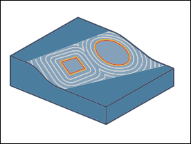
EXTEND_OPEN_INPUT_CURVES
If set to YES, extends the input curve to reach the boundary or the containment to avoid the rollover effect of toolpath. Use this option when the defined input curve is smaller than the surface to be machined.
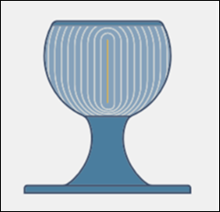
The parameter is set to YES:
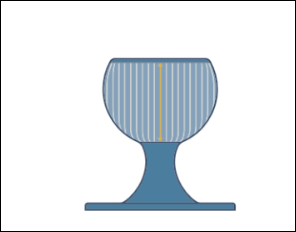
The parameter is set to NO:
Default: NO
FLIP_STEP_OVER
Changes the order of the cuts as follows:
• Outside to inside and vice versa for closed contours.
• Left to right and vice versa for open contours.
Default: NO
MACHINING_AREA
Determines which machining side is used as the step direction:
• SIDE_ONE—The inside area is machined.
• SIDE_TWO—The outside area is machined.
MACHINING_AREA (SIDE_ONE, SIDE_TWO) is supported for Parallel to multiple curves pattern type. |
Default: SIDE_ONE
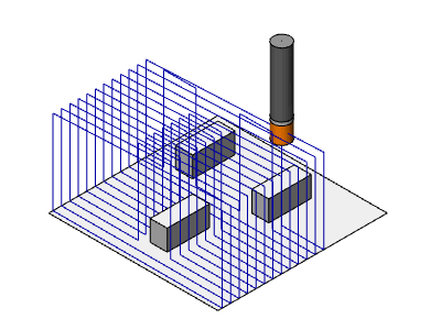
NUMBER_CUTS_ON_SURF
Sets the number of cuts on a surface. When you define a value that is equal to or greater than 1, cuts are created on the guide curves. The distance between two consecutive number cuts is maintained by MAX_STEP_OVER.
For decimal values, only the base or integer is used. For example, for a value of 3.8, only the integer (3) is considered for number of cuts on a surface.
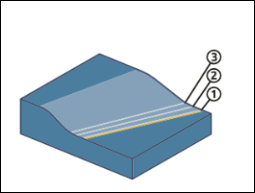
1. Toolpath on the guide curve
2. Second cut
3. Third cut
Default: – (dash)
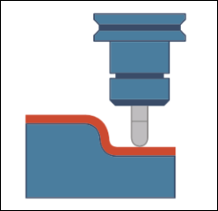
STOCK_ALLOW
Specify the amount of material or stock allowance to remain on the machining surfaces. The offset expands the machining faces in three-dimensions.
For negative value of stock allowance, you must clear the Add machining references check box on the Check Surfaces tab. |
Default: 0
COLLISION_AVOID_OPTION
Avoid toolpath collisions by setting one of the following options:
• TILT—Additional tool tilts are added automatically to avoid toolpath collisions.
• NO_COLISION_CHECK—Collision checks are not performed. The toolpath may contain collisions.

• TRIM_AND_RELINK—Trim all colliding toolpath segments out of the toolpath.
Default: TILT