Create a symbol
Creo Elements/Direct Annotation provides the following types of symbols:
• Edge
• GD & T
The orientation and position of the datum symbols and their reference lines, if drawn, depend on the drawing elements to which they are attached.
The datum targets in particular denote specific points, lines, or areas on a view that are used in establishing a datum reference frame.
The GD & T menu contains the tolerance symbols. You can add modifiers and datums to tolerance symbols to build up geometric tolerance groups.
GD & T symbols are contained in the hp_symbols2 font (which has the filename hp_symbols2.fnt). When you add these symbols to a drawing, Creo Elements/Direct Annotation uses this font.
• Datum
• Datum ANSI
• Datum ISO/DIN
• Datum Target
• Datum Target Area
• Datum Target Point
• Movable Datum Target
• Tolerance
• Moulding
• Surface
• Welding
• User defined
Each of these is created in a separate menu.
To create a symbol,
1. Click Annotation and then, in the Annotate group, click the arrow next to  Symbol.
Symbol.2. Click Create Symbol.
Create Symbol.3. Double-click the desired symbol in the Template Browser or select an existing symbol on the sheet. The dialog box for that symbol appears, displaying the default values, and the symbol appears on the cursor when it is placed in the Creo Elements/Direct Annotation viewport.
4. If needed, click Owner and specify the owner of the symbol.
5. Position the symbol in the viewport.
You can drag the symbol to a new position at any time.
• Eligible reference elements (geometrical entities, dimension text, tolerances, dimension lines, dimension reference lines, and points) to position the symbol are highlighted when you hover over them. • After positioning a surface symbol, you can change its reference element by selecting the symbol and clicking  Change Reference on the CMT. Change Reference on the CMT.• Surface symbols can be grouped with reference elements; if you move the reference element, the symbol is also moved. However, if you make major changes to the reference element, or if the reference element is an angular dimension, you must reattach the symbol using Change Reference. |
6. Complete the operation as described below.
To specify symbol parameters,
1. Choose among the following:
◦ For an edge symbol, specify the following parameters:
Indication | Indicate either the size (  ) or the direction ( ) or the direction ( ) and enter the values for the respective parameters: a, b, c, and d. ) and enter the values for the respective parameters: a, b, c, and d. |
All around | Select to indicate applying the size or direction parameters to extended features that are connected by a closed loop. |
Position | Select the placement of the symbol with respect to the reference line. |
◦ For a Datum symbol, enter a datum text for the symbol in the Datum box.
◦ For a Datum ANSI symbol, enter a datum text for the symbol in the Datum box. Optionally select the position of the symbol on the reference line from the Adjust box.
◦ For a Datum ISO/DIN symbol, enter a datum text for the symbol in the Datum box. Optionally select the position of the symbol on the reference line from the Adjust box.
◦ For a Datum Target symbol, enter a name in the Name box, and/or enter a value in the Value box. To add a diameter symbol (Ø) to the specified value, click the Ø switch on.
◦ For a Datum Target Area symbol, enter a radius for the target area symbol in the Radius box.
◦ For a Datum Target Point symbol, directly place the symbol in the viewport.
◦ For a Movable Datum Target symbol, enter a name in the Name box. Optionally enter a value in the Value box. To add a diameter symbol (Ø) to the specified value, click the Ø switch on.
◦ For a GD & T tolerance symbol, specify the following parameters:
Multiline | Create a multiple-tier tolerance symbol. | ||||
Tolerance | Select the type of tolerance symbol. | ||||
Composite | Create up to four lines of tolerance information (see below). Composite symbols span two or more lines of text in height. | ||||
Value | Click the Value box, the symbol pallet or widget opens. Type the tolerance value. | ||||
Datums | Type or select the Primary, Secondary, and Tertiary datums. To specify multiple datum references, click Primary, Secondary or Tertiary. The symbol pallet or widget opens. Type the datum reference characters. | ||||
Indicators | Select one of the available indicators, Intersection Plane, Direction Feature, Collection Plane and Orientation Plane.
| ||||
Fix text | Click Fix Text. The Fix Text dialog box opens. You can add a prefix, postfix, subfix, and superfix to the symbol. Special characters can be added to fix text. You can also store text in tables for future use. • Click Prefix, Postfix, Superfix, or Subfix to open a text editor. Click Spec Chars to use special characters. Specify the value and click  . Alternatively, type the text in the boxes or select from the list. . Alternatively, type the text in the boxes or select from the list.
• Use the buttons above Superfix and below Subfix to align and add a text box to the superfix and subfix, respectively. • Click Put All to add the current fix text to the all fix texts symbols table. • Click Get All to retrieve predefined fix text from the all fix texts symbols table.
|
In the Composite section, select the number of lines to be added. You can add a maximum of four lines to the composite symbol. Click  and
and  to switch the composite tiers. Following is an example of a composite symbol.
and to switch the composite tiers. Following is an example of a composite symbol.
You can also create a multiple-tier tolerance symbol:

Click Insert in the Parameters section to add another tier to the symbol. Click and to switch tiers. Click Delete to remove a tier.
and to switch tiers. Click Delete to remove a tier.◦ For a moulding symbol,
Two versions of the moulding symbol are available in the Template Browser:
▪  Moulding (ISO 10135–2007)
Moulding (ISO 10135–2007)▪  Moulding Ref Line (ISO 10135–2007)
Moulding Ref Line (ISO 10135–2007)Double-click any one symbol in the Template Browser and specify the following parameters in the respective dialog boxes:
Form | Select the moulding symbol form. Subsequent parameters differ for each form. |
Type a | Select a value for the type of parting surface, type of movable tool part, or type of tool marking depending on the version and form of the moulding symbol. |
b | Enter a value to indicate the angle of the tool motion direction or the draft angle of a surface of a moulded part depending on the version and form of the moulding symbol. |
a | Enter a value to indicate the angle of the part removal direction, the draft angle of a surface of a moulded part, the surface enlargement, the maximum-permissible dimensions of sink marks, or the porosity specification depending on the version and form of the moulding symbol. |
Mismatch b | Enter a value to indicate the maximum-permissible surface mismatch. |
Flash c | Enter a value to indicate the maximum-permissible flash dimensions. |
Flip arrow | Select to flip the part removal direction. |
Alignment | Select the alignment of the origin: at the left, center, or right of the symbol. |
Direction b | Select a value to indicate the direction (elevated, or depressed, or both) of the maximum-permissible deflection caused by the tool marking. |
Dimension c | Enter a value to indicate the dimension of the maximum-permissible deflection caused by the tool marking. |
Flash d | Enter a value to indicate the maximum-permissible flash at a tool marking. |
Count e | Enter the count of reference objects to which a tool marking symbol points. |
Symbol | Select a value to indicate the extended region of a part. |
Inclination | Select the inclination symbol for the draft angle. |
Position | Select the placement of the symbol with respect to the reference line. |
◦ For a Surface symbol,

Five versions of the surface symbol are available in the Template Browser: Surface (ISO 1302–1992), Surface (ISO 21920–2021), Surface (ISO 1302–2002), Surface (ASME Y14.36–2018), and Surface (ISO 25178–2016). Double-click any one symbol in the Template Browser and specify the following parameters in the respective dialog boxes:
Automatic Grouping | Enable or disable automation grouping of symbols with their reference elements when you create surface symbols or change their reference elements. The check box is selected by default if the symbol is snapped to a tolerance or dimension geometry (except extension lines); the check box is cleared by default if the symbol is snapped to an extension line.
| ||
Symbol Location | If the symbol is snapped to dimension text that is not parallel to the dimension line, select either TOP or RIGHT to place the symbol. The default is TOP and left-aligned. | ||
Form | Select the surface symbol form. | ||
Unit of Proposal | Select the unit of proposal. This determines which sets of predefined parameters appear in some menus below. | ||
Finish Val a1 | Enter the upper roughness value.
| ||
Finish Val a2 | Enter the lower roughness value (Surface (ISO 1302–1992)) or middle roughness value (Surface (ISO 25178–2016), Surface (ISO 1302–2002), Surface (ASME Y14.36–2018), and Surface (ISO 21920–2021)).
| ||
Finish Val a3 | Enter the lower roughness value (Surface (ISO 25178–2016), Surface (ISO 1302–2002), Surface (ASME Y14.36–2018), and Surface (ISO 21920–2021)). | ||
Add Surface Finish Rows | Select to add an additional two values for the surface finish or roughness in the Surface (ASME Y14.36–2018) version: Finish Val a4 and Finish Val a5. | ||
Process b | Enter the manufacturing process code. | ||
No. of identical spec. e | Enter the number of identical specifications (Surface (ISO 21920–2021)). | ||
Groove Dir d | Select the groove direction.
| ||
Profile Dir d | Select the profile direction (Surface (ISO 21920–2021)). | ||
Prof. Dir Angle | Enter the profile direction angle (Surface (ISO 21920–2021)).
| ||
Lay & Orient i | Select the surface lay and orientation value (Surface (ISO 21920–2021)). | ||
Surface Lay Indicator Symbol | Select the surface lay indicator symbol (Surface (ISO 21920–2021)). | ||
Surface Lay Indicator Value g | Enter the surface lay indicator value (Surface (ISO 21920–2021)). | ||
Profile Dir. Indicator Symbol | Select the profile direction indicator symbol (Surface (ISO 21920–2021)). | ||
Profile Dir. Indicator Value f | Enter the profile direction indicator value (Surface (ISO 21920–2021)). | ||
Cov Length c | Enter the covered length.
| ||
Measure f | Enter another roughness measure.
| ||
Allowance e | Enter the machining allowance.
| ||
Standard | Select the surface symbol version: ISO (1302–1992), ISO (1302–2002), ISO (21920–2021), ASME Y14.36–2018, or ISO (25178–2016). Depending on the default Standard setting, you can select any one or all the surface symbol versions. See Set default symbol parameters. If the default Standard setting is All, you can change any symbol to the other version. However, • If the default setting is ISO 1302 - 1992, show only, you can only change a Surface (ISO 1302–2002), Surface (ASME Y14.36–2018), or Surface (ISO 25178–2016) symbol to Surface (ISO 1302–1992). • If the default setting is ISO 1302 - 2002, show only, you can only change a Surface (ISO 1302–1992), Surface (ASME Y14.36–2018), or Surface (ISO 25178–2016) symbol to Surface (ISO 1302–2002). • If the default setting is ISO 21920 - 2021, show only, you can only change a Surface (ISO 1302–1992), Surface (ISO 1302–2002), Surface (ASME Y14.36–2018), or Surface (ISO 25178–2016) symbol to Surface (ISO 21920–2021). • If the default setting is ASME Y14.36 - 2018, show only, you can only change a Surface (ISO 1302–1992), Surface (ISO 1302–2002), or Surface (ISO 25178–2016) symbol to Surface (ASME Y14.36–2018). • If the default setting is ISO 25178 - 2016), show only, you can only change a Surface (ISO 1302–1992), Surface (ISO 1302–2002), or Surface (ASME Y14.36–2018) symbol to Surface (ISO 25178–2016). |
Note that the horizontal bar of the symbol is not drawn if none of the b, c, and f values is given for the Surface (ISO 1302–1992) version.
See Examples of how surface symbols are placed in different scenarios.
◦ For a Welding symbol,
Specify the following parameters:
Shape | Select the type of welding symbol. | ||
Position | Select the orientation of the symbol. | ||
Geo Var | Toggle the menu to display the geometric variable fields g1 to g7. Select the required geometry elements from the cascade lists. The elements comply with the DIN 18800-1 standard. | ||
Text Var | Toggle the menu to display the text variable fields t1 to t7. Enter the required values in the data entry fields.
|
If you are modifying a welding symbol, you can click Swap Side to exchange parameters between the arrow side and other side of the welding symbol.
2. Under Appearance, at any time during creation of the text, you may specify various attributes. Most of these settings are intuitive, but it may be helpful to know:
Style: | Select Standard, Datum Target, Generic, Movable Datum Target, or Surface.
| ||
Angle: | Specifies the angle between the text base line and the horizontal. If you set the value of the angle to Auto, Creo Elements/Direct Annotation will use the angle of the selected element to set the angle of the symbol. The Get Angle button will change to Flip Symbol so you can position the symbol on the other side of the element.
| ||
Size: | Whether the size of the symbol is relative | ||
Ratio: | The ratio of character width to height. | ||
Slant: | The deviation from vertical of the characters in the text; values must be between -80 and +80 degrees (approximately ±1.39 rad or ±88.88 grad). | ||
Text: | The color of the text in the symbol. | ||
Geometry: | The color of the geometry in the symbol. | ||
Hatch: | The color of the symbol hatching. | ||
All: | The color of the entire symbol, including the text and geometry. |
3. You may change any parameters for the symbol until you click Position Next Symbol or OK.
4. To add another symbol, click Position Next Symbol, specify its position, and edit as required.
5. Click  to complete the operation.
to complete the operation.The Ref Line button is active when the owner of the symbol is a valid reference line owner (a view or a sketch). Click it to open the Create Ref Line dialog box and draw a reference line from the current symbol to a target element in the drawing.
Limitations
Creo Elements/Direct Modeling splits multiple-tier GD&T symbols into separate symbols when you save your drawing to a format older than 2008.
Examples
The following table lists some examples of placement of surface symbols.
Type of placement | Example |
|---|---|
Symbol location is TOP | 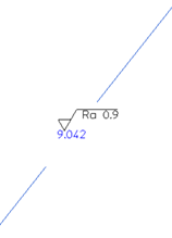 |
Symbol location is RIGHT |  |
Symbol is snapped to geometry | 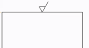 |
Symbol is snapped to geometric tolerance • Single tolerance • Stacked tolerances • Tolerance with fix text | 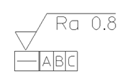 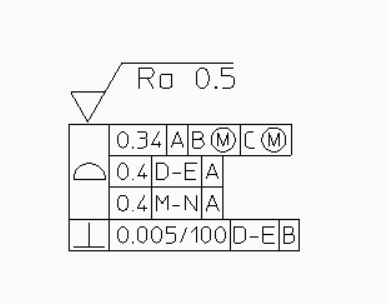 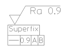 |
Symbol is snapped to dimension text • Dimension text for a horizontal dimension line • Dimension text for a vertical dimension line • Dimension text with fix text | 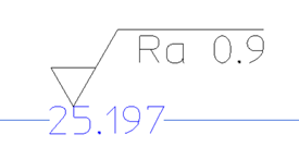 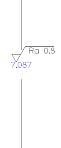 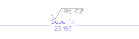 |
Symbol is snapped to dimension line • Linear horizontal dimension line • Linear vertical dimension line • Circular dimension line • Angular dimension line | 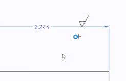 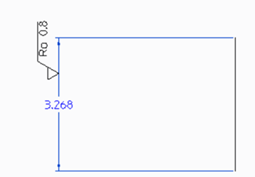 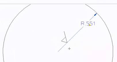 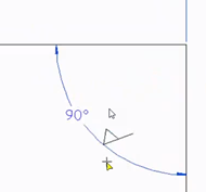 |