If you have created a relation set, you can start creating relations between components and elements. Relations are automatically added to the active relation set, so if you have more than one relation set, you should check which one is active.
1. Click Relations and then, in the Relations Mode group, click Assembly.
2. Click Relations and then, in the Create & Modify group, click Relation. The Relation dialog box opens.
3. Select the two elements for your relation in the viewport.
4. A relation type will be chosen automatically based on the geometry you selected. You can change the relation type to one of the following:
◦ Distance: The two elements will be positioned at the distance you specify from each other.
◦ Coincident: The two elements will be aligned.
◦ Parallel: The two elements will be parallel.
◦ Angle: The two elements will be positioned at the specified angle from each other.
◦ Tangent: The two elements will be positioned tangent to each other.
◦ Perpend: The two elements will be positioned perpendicular to each other.
5. Type a Name for your relation.
6. Other options and settings may be available, depending on the relation type. Click Relations and then, in the Solving group, click Update to see how these options are applied.
◦ Aligned or Anti-Aligned: Select whether the face normals point in the same direction (Aligned) or in opposite directions (Anti-Aligned).
◦ In Front or Behind: Define the relation in the normal direction (In Front) or the opposite direction (Behind).
7. Click OK to complete the operation.
Advanced relation types
You can also create advanced relation types:
1. Click Relations and then, in the Relations Mode group, click Assembly.
2. Click one of the following in the Create & Modify group:
◦ Variable: This is a variable that you can create and use when you define other relations. Please read
Relation variables for more information.
◦ Gear (Click the arrow next to More and, click Gear.): The two radial elements will rotate at a user-defined transmission ratio. Set R1 for the rotation ratio for Elem 1 and R2 for the rotation ratio for Elem 2.
◦ Rack (Click the arrow next to More and, click Rack.): Elem 1 (radial) will rotate along Elem 2 (directional).
◦ Cam (Click the arrow next to More and, click Cam.): Elem 1 (radial, spherical, or toroidal) will move along Cam faces (tangentially connected faces).
◦ Screw (Click the arrow next to More and, click Screw.): The Screw part rotates and moves the Through Hole part along the parts' coincident axes, unless you set the Fixed Hole option described below.
3. Select the two elements for your relation in the viewport.
4. The relation type you choose will determine which of the following fields are displayed:
◦ Flip Dir: Reverses the direction of rotation or translation.
◦ Fixed Axes: The radial part or parts are stationary in 3D space, so the parts will rotate around the defined axes but they will not move.
◦ Radius: This determines how fast the radial part moves along the planar element in a Rack relation. A larger radius turns slower than a smaller radius.
◦ Fixed Hole: Sets the through hole part so it does not move in a Screw relation type and the screw part will rotate and move along its axis. Without this option set, the screw rotates and moves the through hole part.
◦ Pitch: The distance between threads on the screw part in a Screw relation type. Determines how far the moving part travels with each full rotation.
◦ Exclude (Click the arrow next to More and, click Exclude.): Selected objects are excluded from clash checks and physical behavior.
◦ Include (Click the arrow next to More and, click Include.): Selected faces are included for clash checks and physical behavior. Other faces of the part are not checked for clashes and physical behavior.
5. Type a Name for your relation.
6. Click Animate (if available) to see a preview of your relation in motion.
7. Click OK to complete the operation.
Limitations
• Gear, rack, and screw relations are only affected by animation and dynamic positioning. Changes to other relations will not cause a part to move in response to a gear, rack, or screw relation. For example, if we change a distance relation which moves the directional element in a rack relation, the radial element will not move.
 Assembly.
 Relation. The Relation dialog box opens.
 to complete the operation.
 Gear.): The two radial elements will rotate at a user-defined transmission ratio. Set R1 for the rotation ratio for Elem 1 and R2 for the rotation ratio for Elem 2.
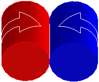
 Rack.): Elem 1 (radial) will rotate along Elem 2 (directional).
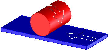
 Cam.): Elem 1 (radial, spherical, or toroidal) will move along Cam faces (tangentially connected faces).
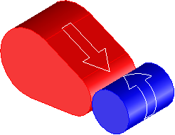
 Screw.): The Screw part rotates and moves the Through Hole part along the parts' coincident axes, unless you set the Fixed Hole option described below.
 Exclude.): Selected objects are excluded from clash checks and physical behavior.
 Include.): Selected faces are included for clash checks and physical behavior. Other faces of the part are not checked for clashes and physical behavior.