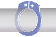
You can easily create grooves for retaining rings you load from Creo Elements/Direct Part Library. You can create grooves for parts that comply with
• DIN 471 (outer ring)
• DIN 472 (inside ring)
• DIN 6799 (outer ring)
By default, grooves are added as user-defined features. You can change this in the Defaults dialog box. Click (dialog box launcher) in the Feature group to open the Default dialog box.
To add a groove with a retaining ring loaded,
1. Click Part Library and then, in the Feature group, click the arrow next to Groove.
2. Click Groove for circlip. The Groove for circlip dialog box opens.
3. Select the Part where you want the groove.
4. Select the Circlip, which is the face that pushes against one side of the groove. This leaves a small gap between the groove and the ring on the other side. The gap is circled in the image below. The supporting face is opposite of the gap, and is perpendicular to the red arrow shown below.
5. Select the Type of groove you want: T1 or T2 (heavy).
6. Click OK to complete the operation.
To add a groove with no retaining ring loaded,
1. Click Part Library and then, in the Feature group, click the arrow next to Groove.
2. Select the type of retaining ring in the Groove on shaft or Groove in hole section. The retaining ring will not be loaded, but an appropriate groove will be created.
3. Select the Shaft or the Bore of the part where you want the groove.
4. Click Size and select a new size from the table, if necessary.
5. Position the groove tool, which is displayed in green in the viewport. This step is easier if you turn on the part to be grooved in the Structure Browser and enlarge the positioning viewport.
 (dialog box launcher) in the Feature group to open the Default dialog box.
 Groove.
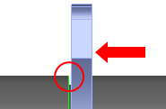
 to complete the operation.