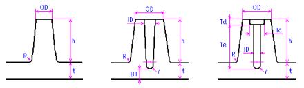
You can create a Solid Boss, Simple Boss, or Screw Boss, shown from left to right below:
The dimensions in the graphic are defined as follows:
Variable
Description
t
Reference wall thickness
ID
Hole diameter
BT
Wall thickness at the bottom of the boss hole
r
Hole blend radius
OD
Boss diameter
h
Boss height
R
Boss blend radius
Tc
Counterbore diameter
Td
Counterbore depth
Te
Thread engagement
The process to create these is similar and is described together:
1. Click Mold Feature and then, in the Plastic Feature group, click Create. The Plastic Feature Browser opens.
2. If necessary, expand the Bosses category in the Plastic Feature browser by clicking the plus sign to its left.
3. Double-click Solid Boss, Simple Boss, or Screw Boss, as required. The relevant creation menu appears.
4. If necessary, select from the Calc Rule list the calculation rule (the group of formulae) used to determine the variables during the calculation of the boss.
5. Click the Center Point of the boss on the model.
6. A direction for the boss is assumed by the Advisor; to change this, click Direction and specify a different direction using the Direction 3D tool.
7. Enter the thickness of the reference wall in the RefW.Thick(t) data entry field.
8. When creating a Simple Boss, enter the hole diameter in the Dia (ID) data entry field.
9. When creating a Screw Boss, enter the screw diameter in the Screw Dia data entry field.
10. To change any of the default parameters (determined by the selected calculation rule):
a. Click Expand on to display the default Boss Data (and Hole Data for simple and screw bosses) in the menu.
b. Enter new values as required. Use the graphic as a guide.
11. Click OKto complete the operation and create the boss.
If any of the parameters you enter breaks a rule, the Advisor issues a warning informing you of the allowable values for the parameter. Click Continue in the Warning box to ignore the warning and accept the value as entered.
While entering parameters, you can always return to the Advisor-determined default values by clicking Default on in the menu. The default values replace all values you have entered.
When Default is on, but you change one of the default parameters, the Default switch is automatically turned off. This tells the system that you are specifying your own defined values from that point on. Therefore, if you subsequently change the RefW.Thick(t), Screw Dia or Calc Rule values, the parameters do not change according to the defaults until the Default option is switched on again.
 Create. The Plastic Feature Browser opens.
 to complete the operation and create the boss.