Produce photo-realistic images of models with Creo Elements/Direct Rendering. Use the Rendering Browser to select from a large variety of materials on which to base the look of your part or assembly. Adjust lighting and provide scenes for your model, too. Use rendering archives to save settings you have defined for future use. Save your rendered images to JPG, BMP, or TIFF files.
To activate the Rendering module:
1. Click File > Modules. The Modules dialog box opens.
2. On the Modules pane, click Rendering (under free).
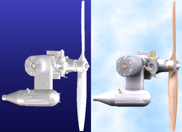
Note the difference between the rendered (right) and unrendered (left) models below.
Creo Elements/Direct Rendering includes Realtime and Photo-realistic modes.
Realtime rendering overview
With Realtime rendering you can watch your model take on the material and scene attributes you select as you assign them. This mode starts automatically when activating the Creo Elements/Direct Rendering. Here you can assign materials to parts or faces, as well as assign lights, background, foreground, and other scenery. Realtime mode provides a viewport preview of your model while letting you conduct other normal modeling and viewing operations.
Highlights and limitations
Highlights
• NVIDIA Cg or OpenGL 2.0 shading language implements per-pixel material and lighting calculations.
• Texture and bump mapping, along with varying reflection models, and provide realistic-looking materials.
• Alpha transparency provides continuous levels of transparency.
• The models can cast and receive shadows.
Limitations
• Not all materials are rendered using per-pixel calculations.
• Not all light types are supported and Creo Elements/Direct Rendering ignores the unsupported light types.
• High resolution printing is not supported.
• Refractions do not allow light direction to change, and materials will always appear semi transparent.
• Render materials do not display when clipping planes are active.
Hardware
Realtime rendering involves resource-intensive calculations. Graphics hardware that is more modern, of higher quality, and with more dedicated memory will perform faster and render images of higher quality than older, slower hardware. If you experience severe performance issues with your current graphics hardware, you can use the Simplified and Faster Rendering mode. The redraw mode of Simplified and Faster Rendering is less resource-intensive and can be set in the RenderingSettings dialog box of Creo Elements/Direct Modeling. You can click File > Settings > Rendering Settings to open Rendering Settings dialog box
Photo-realistic rendering overview
The Photo-realistic mode starts when you click Render. Creo Elements/Direct Modeling generates a high-quality image based on the material, lighting, and scene attributes you assigned. Because the ray tracing calculations used to generate the image usually require some time to complete, no normal modeling or viewing operations may be conducted in this mode. If you click a new command or change the camera, the mode automatically switches to Realtime mode, and the high-quality rendered image is lost (unless you are rendering your image to a file).
Highlights and limitations
Highlights
• Physically correct reflection and refraction calculations are provided by the ray-tracing algorithm.
• Unlimited numbers of light sources of many different types can be defined using either empirical models or physically correct definitions. The former offers an easy method to define lights, whereas the latter provides physically correct light simulations.
• Tone mapping ensures that scenes rendered using physically accurate lighting appear as the human eye sees them.
• Calculation of colored hard and soft shadows.
• Global illumination technologies allow better simulation of indirect illumination.
• Advanced anti-aliasing technologies.
Limitations
• Creo Elements/Direct Modeling only renders solid 3D model geometry. Nothing else can be rendered, including the following:
◦ Wire parts
◦ Edges
◦ Vertices
◦ Workplanes and 2D geometry
◦ Creo Elements/Direct Finite Element Analysis information
◦ Documentation information such as labels and feature points
◦ Drawings
◦ Coordinate systems
• The viewport's Show Settings have no effect on the output.
• Creo Elements/Direct Rendering does not consider clipping planes and cannot render surface or draft angle analysis results.
Settings
Right-click in the viewport and select Rendering Settings to adjust this module's settings. You can also click File > Settings > Rendering Settings to open Rendering Settings dialog box and adjust the Rendering module settings.