The Position command gives you several options for moving parts and assemblies. You can
• Align two parts or assemblies.
• Move a part or assembly in any direction.
• Rotate a part around any axis.
• Apply specialized positioning methods, such as Match 3 Points, Pt Dir Pt, or by a reference coordinate system (By Ref CS).
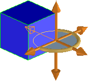
The easiest way to position parts is to manipulate them directly in the viewport, using on-screen helpers called CoPilots. The CoPilot changes when you select different types of geometry. For example, the 3D CoPilot is available when you select an edge:
Drag the 3D CoPilot direction arrows to move the selected part. The 3D CoPilot snaps to any 3D object, 2D geometry, or construction geometry except a 2D spline. As you drag the 3D CoPilot direction arrow, you can:
• Press F5 on the keyboard to toggle the visibility of the 3D geometry in the viewport.
• Press F6 on the keyboard to toggle between the 3D geometry view and the wireframe view.
To position a part, assembly, or workplane set,
1. Click Structure and then, in the Part & Assembly group, click the arrow next to Position.
2. Click Dynamic, Align, Align Axis, Mate, Parallel, 2 Points to select the type of the positioning operation. The Position dialog box opens.
3. Select from the following options:
◦ Direct: Select and move any object in the viewport.
◦ Selected: Restricts movement to the object selected.
◦ Objects: The object to move with positioning options that require a selection. To move an assembly, click Objects then select the assembly in the Structure Browser.
◦ Transform Owner: Selects the owner assembly when you select all its individual parts in the viewport.
You can press SHIFT and select individual parts in the assembly, or box-select individual parts in the assembly.
If the owner assembly contains workplane sets, view sets, or docuplane sets, Creo Elements/Direct Modeling displays a warning and positions the workplanes, view sets or docuplane sets along with the owning assembly.
4. The Methods section allows you to choose the type of positioning operation you want to perform:
◦ Dyn Pos: Move parts or assemblies in the viewport with on-screen tools that are appropriate for the type of object you select.
◦ Mate Align: Move parts into position with respect to another part. See the link below for more information.
◦ Two Points: Select two points in the viewport to move your part or assembly.
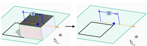
◦ Dimension: Allows you to move a face or feature by changing the value of a dimension created using 3D Documentation. Only available from the Move command.
◦ Other: Restricts movement to the type of movement you select. Move the object in the viewport after you select one of the following options:
▪ Line/Axis: Move the object you select in the viewport in a linear direction.
▪ Plane: Move the object you select in the viewport anywhere on a plane.
▪ Plane by 3 Points: Move the object along a plane that you define by selecting three points on objects in the viewport. Only available if you use Selected.
▪ Rotate: Rotate the object you select in the viewport.
▪ Normal: Move the object you select in the viewport in the normal direction. This is a linear movement.
▪ Radial: Choose an axis. Specify a reference position toward which to move the object. When all reference positions are specified you can move the objects with the 3D Copilot or by typing in the offset value.
▪ Free: Drag the object you select anywhere in the viewport.
▪ Match 3 Points: Positions the object based on three points you select in the viewport.
▪ Pt Dir Pt: Positions the object based on a point, a direction, and another point that you select in the viewport.
▪ Pt Dir Dir: Positions the object based on a point, and two directions (along z axis and x axis) that you select in the viewport.
▪ By Ref CS: Positions the part based on a coordinate system.
◦ If you select Dyn Pos, Dimension, or one of the Other options, you may also choose some of the following options. Only the options that are appropriate for the type of positioning are available:
▪ Direction: Sets the direction to move the object. Click Direction and set a direction in the viewport. Press the TAB key to reverse the direction.
▪ Length: Type a value in this field to set the distance that the object is moved. You can also move the part in the viewport.
▪ Rot. Axis: Rotate the object along an axis you select in the viewport.
▪ Rot. Angle: First select Rot. Axis, then type a value in this field to set the angle that the object is moved.
▪ Fix Dir/Axis: Prevents the axis and direction from changing during positioning. Only allows you to rotate an object.
▪ Ang. by 2 Pts: First select a Rot. Axis, then you can use this method to rotate the part by selecting a start and end point.
▪ Center Axis: Sets the central axis for moving parts via the radial method.
▪ Radial Offset: The distance from the axis that the parts will move.
▪ Ref. Focus: Restricts the selection focus to the element type you select. This is helpful when you want to select a reference element in a complex area of the model.
▪ Values: All values you enter in the dialog will be considered absolute (based on the original position) or relative (based on the current position).
◦ If the Adv Assembly module is active, you will see the following options:
If you choose Mate Align in the Methods section, you can toggle Advanced if Adv Assembly is active. You can clear Advanced and use only the basic Mate Align positioning method.
▪ Stop at Clash: Does not allow you to move an object if it touches another object. The visual feedback displays the color for Touch in
3D CoPilot settings.
▪ Update Relations: All relation sets are solved immediately after you position an object.
▪ Physical: Simulates physical movement in the viewport. For example, if you drag an object, and it bumps into another object, it will go around the other object.
5. Click on the small blue sphere to return the part to its original position. The small green sphere shows you where you clicked on a part, and follows your cursor in the viewport.
6. Click Back to undo one step.
7. Click Re-Apply to instantly apply the last action to your current model without re-entering the information.
8. Click to complete the operation.
Undo reverts all the changes you made while the Position dialog was open. Use the Back button in the Position dialog to remove only one step.

 Position.
 to complete the operation.