Reconcile an existing BOM with a model
Your company may have a process of creating a BOM manually before a project begins and then passing the information on to the designers to create the drawing or model based on the BOM. After the designer creates the drawing or model, use Scan BOM to compare the Masterdata you created in the BOM with the items the designer created. If the two differ, you may need to reconcile the structure that the designer created with that existing BOM.
|
Steps
|
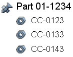
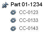
Example 1: BOM and part match
|
Example 2: BOM and part do not match
|
|---|---|---|
|
1. Project manager creates a BOM.
|
 |
 |
|
2. Designer creates the modeled part.
|
 |
 |
|
3. Designer saves the part to Creo Elements/Direct Model Manager.
|
A1 links to Part 01-1234
P1 links to CC-0123
P2 links to CC-0133
P3 links to CC-0143
|
A1 links to Part 01-1234
P1 links to CC-0123
P2 links to CC-0133
A2 not linked
P3 not linked
P4 not linked
|
|
4. Scan the assembly structure to derive the BOM.
The scan compares the existing BOM created by the project manager with the part created by the designer and identifies the differences.
|
Existing Masterdata and designed components match.
No manipulation needed.
|
Existing Masterdata and designed components do not match for CC-0143, A2, P3, and P4.
|
When the existing BOM and the newly created part do not match, reconcile the two. In the example, the project manager and designer must determine how to reconcile the BOM and the modeled part.
To reconcile the differences, they can:
• Use the BOM Editor to create new Masterdata for A2, P3, and P4, or accept the Scan BOM reconciliation changes.
• Link Masterdata CC-0143 with A2.
To reconcile an existing BOM with a model,
Depending on the results of the Scan BOM,
• Accept the Scan BOM reconciliation changes. Scan BOM will create and link the necessary Masterdata to match the designed model structure.
• In the BOM Editor, drag and drop the part onto the Masterdata to link the two together.
• In the BOM Editor, create new Masterdata for the additional parts. > .