The Creo Elements/Direct Modeling object model follows familiar design patterns that are also used in other major applications. Among others, it includes objects representing the Creo Elements/Direct Modeling application, documents, model structure, geometry and topology.
You can find complete documentation on all currently available objects in the online documentation for the CoCreate and CoCreate.Osdm namespaces. In the following, we will discuss the design of the object model and give general guidelines on its usage.
COM clients always operate on interface pointers, while .NET clients typically work with objects (although they can also use an interface-based approach). The Creo Elements/Direct Modeling object model provides object access for .NET clients and interfaces for all objects for COM clients. Classes and interfaces are usually provided in pairs. For example, there is an IPart interface and a Part class that implements that interface.
Most of the time, the functionality for the object and the associated interface is identical. In a few cases, an object implements multiple interfaces, and sometimes there are minor differences due to requirements of the .NET platform.
The only externally instantiable object in the object model is the server object, COsdmServer. In order to distinguish multiple installed versions of Creo Elements/Direct Modeling on any given system, major releases of Creo Elements/Direct Modeling will assign new GUIDs to the server object.
Clients which use the server object GUID explicitly for instantiation will not be able to instantiate future versions of Creo Elements/Direct Modeling. If a client needs more flexibility, there are two approaches:
Note that various types of servers implement the Creo Elements/Direct Modeling object model:
External clients which need control over the type of server which is to be instantiated should use the external startup helper utility.
A note of warning: We expect the currently available object model interfaces to evolve rapidly. We can therefore not guarantee full binary compatibility with versions following CoCreate Modeling 2007.
In many interfaces, there are member functions or properties returning interface pointers which can be used to traverse the structure beneath the current object, or to represent additional data belonging to the current object. In such cases, the server will call AddRef on the interface pointer before returning it. It is the client's responsibility to call Release when it no longer uses the interface pointer. If the client does not release the interface pointer, neither the object behind it nor the resources that the object holds can be deleted. Also, when Creo Elements/Direct Modeling operates as a COM server in the background, it will not be able to shut down automatically as long as there are any outstanding references to any of its objects.
Unless stated otherwise in the documentation for a particular API, all geometric data exposed by the API is represented in Creo Elements/Direct Modeling's internal system units:
API functions returning an array of objects typically return a typed array. For example:
These arrays implement the standard IEnumerable interface and can thus be used for any enumeration strategy familiar to you and common to your programming language of choice. While a C++ COM client is likely to use a for loop to run over the array and access each element, a VB or C# client can use foreach style iteration semantics.
The OsdmServer object is the only object in the API which can be instantiated
externally using CoCreateInstance. It is used
to start up or contact the Creo Elements/Direct Modeling application (see
examples above). Its main purpose is to provide instantiation services for internal
and external clients. You can then use it to inquire an interface pointer to the main
application interface, IApplication.
This is the root of the object model. After instantiation, most applications will start with this interface and use it to drill down into the hierarchy. The interface provides services such as:
Except for loading data files, most clients will use the IApplication
interface to get to the currently active 3D document.
The Application object also implements IFrame.
IFrame provides functionality to register an add-in with Creo Elements/Direct Modeling's
UI.
Add-in menu buttons can also be configured to run Lisp commands. This can be used to implement a flexible and deep integration of the add-in into Creo Elements/Direct Modeling, providing standard Creo Elements/Direct Modeling behavior to the user. The Add-in wizard can generate boilerplate code to get you started with this integration technique. See Integrating add-ins and Lisp for more details.
This interface encapsulates functionality to access the currently active 3D document. For most clients, the most important member function is InqIRootComponent, which can be used to inquire the root-level component in the 3D model from where clients can traverse the currently loaded assemblies.
Structure objects are objects that build the model's structure graph. They are visible in Creo Elements/Direct Modeling's "Graphical Structure Browser" on the left side of the application window. Examples for structure objects are assemblies, parts, containers, coordinate systems, workplanes and more.
The base interface for all structure objects offered through the API is IComponent, which provides functions to navigate the structure tree, find out about relations between components, and provides properties for the component name, transformation and more. In the current version, the API offers these component objects:
The API does not yet offer support for all structure objects available in the Creo Elements/Direct Modeling application and future API versions are likely to extend this list of supported types.
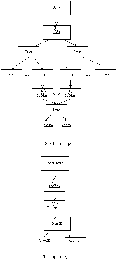
The Creo Elements/Direct Modeling .NET API uses familiar b-rep terms to describe topology and geometry. The root of the topology structure is a Part's Body. From here, you can traverse the topological structure in this order:
For 2D geometry, the root of the topology structure is a Workplane's PlanarProfile. From here, you can traverse the 2D topological structure in this order:
There is no Face2D representation
in 2D topology. The planar profile can contain one or many loops. Each loop
of the profile defines a single profile element. A loop may have one or
more coedges. For example, if a profile has a 2D rectangle and a 2D circle,
the profile will have two loops. 2D construction geometry is not supported
in this release.
The geometry of a 3D face is represented by a TrimmedSurface. A trimmed surface is owned by exactly one face and represents a bounded area on the underlying surface. This surface may be shared by multiple trimmed surfaces.
Similarly, the geometry of an edge (both 2D and 3D) is represented by a TrimmedCurve. A trimmed curve is owned by exactly one edge and describes a bounded segment of the underlying Curve. This curve may be shared by multiple trimmed curves. For 2D geometry the supported curve types are BSpline2D, Line2D and Circle2D.
When accessing the trimmed surface or trimmed curve objects, you must
choose a geometric representation which you are interested in. You can
request either native or external
CurveRepresentation or
SurfaceRepresentation
The native representation gives access to the internal geometry used in Creo Elements/Direct Modeling, including complex types like ProceduralCurves or spun and swept BSpline surfaces.
If you are unfamiliar with these special geometric representations or
your code cannot process them, you may want to choose the external
geometric representations. In these representations, some internal
geometric types are represented as approximated BSpline curves/surfaces,
thus making them easier to handle for the client. See
SurfaceRepresentation
and CurveRepresentation
for details.
3D Faces also provide access to their tesselation data, which can either be used for graphical purposes or as an approximation of their geometry.
Often model entities are shared and thus appear more than once in a model. A SelectionItem is used to select a particular instance of this entity. Typically, you will encounter selection items when receiving a user selection as input. See Integrating add-ins and Lisp for details.
Selection items can also be created by calling CreateISelectionItem in the IDocument3D interface.
Not all types of entities can be referred to using a selection item. Entities which support this feature implement the ISelectable interface.
It is possible to attach custom attributes to entities. These custom attributes can be filled with a list of key-value pairs. Supported value types are strings, integer values, floating-point values and 3D vectors. Custom attributes are identified by a name which must be unique amongst all attributes attached to the owning entity.
Unless the attribute is explicitly created or marked as transient, creating, deleting or modifying an attribute is a model-changing operation which is only possible if the owning entity of the attribute is modifiable.
To assure that changes made through the API persist with the model, set the owning entity's state to modified. Failure to do so will likely result in losing changes made via the API. It is, however, sufficient to flag the entity as modified just once after a series of modifications on one or more attributes attached to this entity.
There are two approaches to create and find attributes:
API attributes are designed to be fully compatible with user-defined attributes which were attached to the model using Developer's Kit functionality, i.e. attributes can be created in Lisp and subsequently read or modified through the API, or vice versa.
Sheet Metal features attached to a part can be inquired via the SheetMetalPart interface. The following sheet metal features are supported:
Advanced operations with SheetMetal features can be done using SheetAdvisorUtilities object.
3D transformations are represented in the API with the (I)Transform3D interface/class. They describe rotations, translations, mirror and scaling operations or combinations of these, where scaling is restricted to the same factor for all 3 dimensions, using a 4x4 matrix.
Transformations are a member of each model Component. In a component tree, a component's transformation describes the position of a component relative to its direct parent.
In most cases, geometric data of a model part are expressed in that part's local coordinate system (LCS). This data can be transformed into the parent's LCS by multiplying the local transformation of this part to the data. This operation can be repeated until reaching the root component. This will have transformed the data from a parts LCS into the world coordinate system (i.e. the coordinate system of the root component, aka. global coordinate system or WCS). The accumulated transformation from the LCS to the WCS is often called the global transformation. This global transformation can also be directly inquired from a SelectionItem object.
Most functions in the API expose 3D vectors as separate x, y and z components. For calculation purposes, such as multiplying a Transform3D to the vector, calculating dot or cross vector products etc., use the Vector3D object which can easily be created from the x, y and z components using MathUtility.CreateVector3D
The API exposes 3D points as separate x, y and z components. For calculation purposes, (I)Transform3D provides a method to transform a 3D point.
Many model elements such as components, edges, faces etc. provide a BoundingBox property describing an axis-parallel box containing the entity's geometry (in LCS). Also, Box3D object can be instantiated from arbitrary values and modified by many operations offered in the Box3D object. Together with the provided box comparison functions, this allows rough and fast clash tests between entities, or to define regions-of-interest in advanced clearance measurement functions.
The (I)MathUtility interface/class provides methods to create custom instances of Transform3Ds, Vector3Ds and Box3Ds.
TrimmedCurve and TrimmedSurface as well as Curve and Surface objects and their derived types offer a rich set of calculation and evaluation functions for this one geometric element.
The (I)GeoMathLib interface/class provides advanced, performance-optimized geometric calculation routines, for example to calculate clearances amongst one or more sets or entities.
The (I)SheetAdvisorUtilities interface/class provides advanced and highly-specialized functions related to working with SheetMetal parts.
The (I)Modeler interface/class provides various methods to create temporary curves, surfaces, edges and faces from existing model entities, other temporary objects or freely defined geometries. Temporary objects can also be modified with transformation or offset operations.
Temporary objects do not become part of the actual 2D or 3D model. They are transient objects which only exist as long as the client holds a reference to them. They would typically be used in calculations, i.e. in functions provided by the GeoMathLib.
Special lifetime rules apply for temporary objects: