Example: Surface Polygons and Other Connected Annotations
You can connect annotations to MCAD parts or ECAD component instances. An MCAD example follows below.
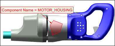
In the Model View, you may want to draw a polygon on the surface of one or more parts, and then annotate them with notes. For a note that references parts, you can insert text that is automatically determined by the attributes of the connected parts.
The connection between the notes, leader lines, surface polygons, and parts is maintained when you move the corresponding parts. A note can be connected to any number of items. When you create a new note connected to a surface polygon, the note’s color and line style are automatically set to match the surface polygon. Each vertex on the polygon is attached to a surface point on the part. See the table below to see the results of performing actions on the polygon or on the parts:
Action | Result |
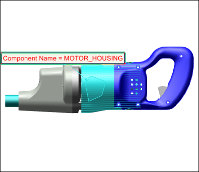
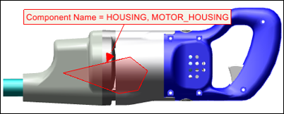
Select the polygon | Selects the polygon and highlights the corresponding parts, notes, and leader lines using the secondary highlighting color: |
Move the corresponding part | Moves the annotations with the part |
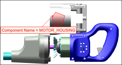
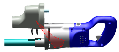
Rotate the corresponding part | Appears as a wireframe from behind: |
Drag a vertex | Moves the vertex, and attaches it to the new surface point. Updates connected notes if necessary: |
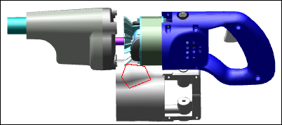
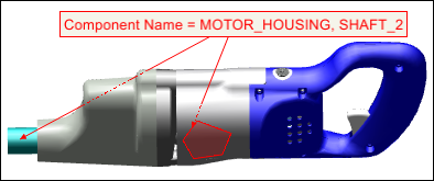
For polygons that span two or more parts, move one of the corresponding parts | Stretches the polygon: |
Connect a note to more than one item with different attribute values | Lists the values, separated by commas: |