|
Analysis Type:
|
Static
|
|
Model Type:
|
2D Axisymmetric
|
|
Comparison:
|
NASTRAN No. V2411
|
|
Reference:
|
• P.E. Grafton and D.R. Strome, "Analysis of Axisymmetrical Shells by the Direct Stiffness Method," AIAA Journal, 1(10): 2342-2347.
• J.W. Jones and H.H. Fong, "Evaluation of NASTRAN," Structural Mechanics Software Series, Vol. IV (N. Perrone and W. Pilkey, eds.), 1982.
|
|
Description:
|
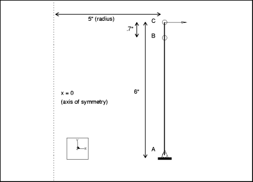
Find the radial deflection at the loaded end of a cantilever cylinder that is modeled axisymmetrically.
|

Element Type: | 2D shell (2) | |
Units: | IPS | |
Dimensions: | length: 6 radius: 5 thickness: 0.01 | |
Material Properties: | Mass Density: 0 Cost Per Unit Mass: 0 Young's Modulus: 1e7 | Poisson's Ratio: 0.3 Thermal Expansion: 0 Conductivity: 0 |
Constraint: | placed on point A: fixed in all DOF | |
Load: | placed on point C: FX = 1 Distribution: N/A Spatial Variation: N/A | |
Theory | MSC/ NASTRAN | Structure | % Difference | |
Radial Deflection @ Load (a=disp_x_radial) | 2.8769e-3 | 2.8715e-3 | 2.8725e-3 | 0.15% |
Convergence %: 0.5% on Local Disp and SE | Max P: 7 | No. Equations: 33 | ||
Analysis Type: | Static |
Model Type: | 2D Axisymmetric |
Comparison: | ANSYS No. 15 |
Reference: | Timoshenko, S. Strength of Materials, Part II, Advanced Theory and Problems. 3rd ed. NY: D. Van Nostrand Co., Inc. 1956, pp. 96, 97, and 103. |
Description: | A flat circular plate, modeled axisymmetrically, is subjected to various edge constraints and surface loadings. Determine the maximum stress for each case. |

Element Type: | 2D shell (1) | |
Units: | IPS | |
Dimensions: | radius: 40 thickness: 1 | |
Material Properties: | Mass Density: 0 Cost Per Unit Mass: 0 Young's Modulus: 3e7 | Poisson's Ratio: 0.3 Thermal Expansion: 0 Conductivity: 0 |
Constraints: | Location | Degrees of Freedom |
clamped | placed on point B: | fixed in all DOF |
simple | placed on point B: | fixed in TransX and TransY |
Loads: | Location/Magnitude: | Distribution: | Spatial Variation: |
clamped | placed on edge A-B: FY = 6 | per unit area | uniform |
simple | placed on edge A-B: FY = 1.5 | per unit area | uniform |
Theory | ANSYS | Structure | % Difference | |
Maximum Stress (m=max_prin_mag, a=clamped) | 7200 | 7152 | 7200 | 0.0% |
Convergence %: 0.0% on Local Disp and SE | Max P: 5 | No. Equations: 15 | ||
Maximum Stress (m=max_prin_mag, a=simple) | 2970 | 2989 | 29701 | 0.0% |
Convergence %: 0.0% on Local Disp and SE | Max P: 5 | No. Equations: 16 | ||
Analysis Type: | Static |
Model Type: | 2D Plane Stress |
Comparison: | NASTRAN No. V2408A |
Reference: | Singer, Ferdinand L. Strength of Materials. Harper & Row, 1962, Art. 52, p. 133. |
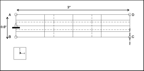
Description: | Find the bending stress at the fixed end for a cantilever plate subjected to an in-plane shear load. |
Element Type: | 2D plate (1) | |
Units: | IPS | |
Dimensions: | length: 3 height: 0.6 thickness: 0.1 | |
Material Properties: | Mass Density: 0 Cost Per Unit Mass: 0 Young's Modulus: 1.07e7 | Poisson's Ratio: 0 Thermal Expansion: 0 Conductivity: 0 |
Constraints: | placed on edge A-B: fixed in TransX, TransY | |
Loads: | placed on edge C-D: FY= –200 Distribution: per unit length Spatial Variation: uniform | |
The theoretical results are based on elementary beam theory. Structure models the actual physical structure, capturing the singular stresses present at the constrained corners. Setting Poisson's ratio equal to zero reduces the model to its elementary form. | ||
Theory | MSC/ NASTRAN | Structure | % Difference | |
Bending Stress @ Node A (m=max_stress_xx) | 6.0e4 | 5.5190e4 | 6.0121e4 | 0.20% |
Convergence %: 0.0% on Local Disp and SE | Max P: 4 | No. Equations: 22 | ||
Analysis Type: | Static |
Model Type: | 2D Plane Strain |
Comparison: | The MacNealHarder Accuracy Tests |
Reference: | MacNeal, R.H., and Harder, R.L. "A Proposed Standard Set of Problems to Test Finite Element Accuracy." Finite Elements in Analysis and Design I. Elsevier Science Publishers, 1985. |
Description: | A thick-walled cylinder, modeled symmetrically, is loaded with unit internal pressure. Find the radial displacement at the inner radius for two nearly incompressible materials. |

Element Type: | 2D solid (1) | |
Units: | IPS | |
Dimensions: | outer radius: 9.0 inner radius: 3.0 | |
Material Properties: | Mass Density: 0 Cost Per Unit Mass: 0 Young's Modulus: 1000 | Poisson's Ratio: • 0.49 (case 1) • 0.499 (case 2) |
Constraints (UCS): | placed on edges A-B & C-D: fixed in all DOF except TransR | |
Loads: | placed on edge A-D: pressure load = 1 Distribution: N/A Spatial Variation: uniform | |
Theory | Structure | % Difference | |
Radial Displacement @ Inner Radius (case 1) (m=rad_disp) | 5.0399e-3 | 5.0394e-3 | <0.01% |
Convergence %:1% on Local Disp and SE | Max P: 6 | No. Equations: 38 | |
Radial Displacement @ Inner Radius (case 2) (m=rad_disp) | 5.0602e-3 | 5.0553e-3 | 0.09% |
Convergence %: 1.0% on Local Disp and SE | Max P: 6 | No. Equations: 38 | |
Analysis Type: | Static |
Model Type: | 2D Axisymmetric |
Comparison: | NASTRAN No. V2410 |
Reference: | Crandall S.H., Dahl N.C. , and Larnder T.J. An Introduction to the Mechanics of Solids. 2nd ed. NY: McGraw-Hill Book Co., 1972, pp. 293-297. |
Description: | Find the stress at radii r = 6.5" and r = 11.5". A thick-walled cylinder is modeled axisymmetrically and subjected to internal pressure. |

Element Type: | 2D solid (3) | |
Units: | IPS | |
Dimensions: | inner radius: 6 height: 8 thickness: 6 | |
Material Properties: | Mass Density: 0 Cost Per Unit Mass: 0 Young's Modulus: 3e7 | Poisson's Ratio: 0 Thermal Expansion: 0 Conductivity: 0 |
Constraints (UCS): | placed on edges A-D & B-C: fixed in TransY and RotZ | |
Loads: | placed on edge A-B: pressure load = 10 Distribution: per unit area Spatial Variation: uniform | |
Theory | MSC/ NASTRAN | Structure | % Difference | ||
@ r = 6.5 | Stress Radial (m=r6_5_radial) | -8.03 | -8.05 | -7.9720 | 0.72% |
Stress Hoop (m=r6_5_hoop) | 14.69 | 14.73 | 14.69 | 0.0% | |
@ r = 11.5 | Stress Radial (m=r11_5_radial) | -0.30 | -0.30 | -2.6636e-1 | 0.0% |
Stress Hoop (m=r11_5_hoop) | 6.96 | 6.96 | 6.96 | 0.0% | |
Convergence %: 0.25% on Local Disp and SE | Max P: 4 | No. Equations: 54 | |||
Analysis Type: | Static |
Model Type: | 3D |
Comparison: | NASTRAN No. V2405 |
Reference: | Roark, R.J., and Young, W.C. Formulas for Stress and Strain. NY: McGraw-Hill Book Co., 1982, p. 96. |
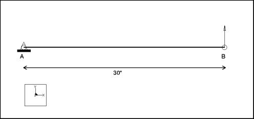
Description: | A cantilever beam is subjected to a load at the free end. Find the deflection at the free end and the bending stress at the fixed end. |
Element Type: | beam (1) | |
Units: | IPS | |
Dimensions: | length: 30 | |
Beam Properties: | Area: 0.310 IYY: 0.0241 Shear FY: 1000 1 CY: 0.5 | J: 0.0631 IZZ: 0.0390 Shear FZ: 1000 1 CZ: 0.375 |
Material Properties: | Mass Density: 0 Cost Per Unit Mass: 0 Young's Modulus: 1.0e7 | Poisson's Ratio: 0.3 Thermal Expansion: 0 Conductivity: 0 |
Constraints: | placed on point A: fixed in all DOF | |
Loads: | placed on point B: FY = 100 Distribution: N/A Spatial Variation: N/A | |
Theory | MSC/ NASTRAN | Structure | % Difference | |
Deflection @ Tip (m=max_disp_y) | 2.3077 | 2.3077 | 2.3094 | 0.073% |
Bending Stress @ Fixed End (m=max_beam_bending) | 38461 | 38461 | 38461 | 0.0% |
Convergence %: 0.0% on Local Disp and SE | Max P: 4 | No. Equations: 24 | ||
Analysis Type: | Static |
Model Type: | 3D |
Comparison: | ANSYS No. 2 |
Reference: | Timoshenko, S. Strength of Materials, Part I, Elementary Theory and Problems. 3rd ed. NY: D. Van Nostrand Co., Inc., 1955, p. 98, Problem 4. |
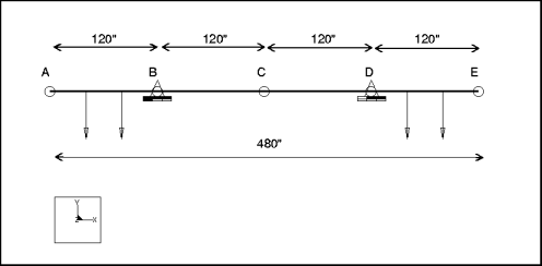
Description: | A standard 30" WF beam, supported as shown below, is loaded on the overhangs uniformly. Find the maximum bending stress and deflection at the middle of the beam. |
Element Type: | beam (4) | |
Units: | IPS | |
Dimensions: | length: 480 | |
Beam Properties: | Area: 50.65 IYY: 1 Shear FY: 0.8333 CY: 15 | J: 7893 IZZ: 7892 Shear FZ: 0.8333 CZ: 15 |
Material Properties: | Mass Density: 0 Cost Per Unit Mass: 0 Young's Modulus: 3e7 | Poisson's Ratio: 0.3 Thermal Expansion: 0 Conductivity: 0 |
Constraints | Location | Degrees of Freedom |
placed on point B: placed on point D: | fixed in all DOF except RotY and RotZ fixed in TransY and TransZ |
Loads | Location/Magnitude | Distribution | Spatial Variation |
placed on edge A-B: FY = 833.33 placed on edge D-E: FY = 833.33 | per unit length per unit length | uniform uniform |
Theory | ANSYS | Structure | % Difference | |
Max Bending Stress @ Middle (m=max_beam_bending) | 11400 | 11404 | 11403.91 | 0.03% |
Max Deflection @ Middle (m=disp_center) | 0.182 | 0.182 | 0.182 | 0.0% |
Convergence %: 0.0% on Local Disp and SE | Max P: 4 | No. Equations: 96 | ||
Analysis Type: | Static |
Model Type: | 3D |
Comparison: | The MacNealHarder Accuracy Tests |
Reference: | MacNeal, R.H., and Harder, R.L. "A Proposed Standard Set of Problems to Test Finite Element Accuracy." Finite Elements in Analysis and Design I. Elsevier Science Publishers, 1985. |
Description: | A straight cantilever beam, constructed of parallelogram-shaped elements, is subjected to four different unit loads at the free end, including • extension • in-plane shear • out-of-plane shear • twisting loads Find the tip displacement in the direction of the load for each case. |
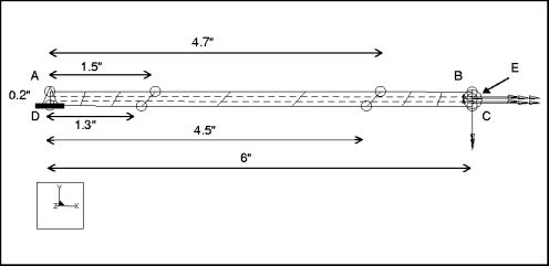
Element Type: | shell (3) | |
Units: | IPS | |
Dimensions: | length: 6 width: 0.2 thickness: 0.1 | |
Material Properties: | Mass Density: 0 Cost Per Unit Mass: 0 Young's Modulus: 1e7 | Poisson's Ratio: 0.3 Thermal Expansion: 0 Conductivity: 0 |
Constraints: | placed on edge A-D: fixed in all DOF | |
Loads: | Location/Magnitude: | Distribution: | Spatial Variation: |
extension | placed on edge B-C: FX = 1 | total load | uniform |
in_plane | placed on edge B-C: FY = 1 | total load | uniform |
out_plane | placed on edge B-C: FZ = 1 | total load | uniform |
twist | placed on point E: MX = 1 | total load | N/A |
Theory | Structure | % Difference | |
Tip Disp. in Direction of Load (l=extension, m=max_disp_x) | 3e-5 | 2.998e-5 | 0.06% |
Tip Disp. in Direction of Load (l=in_plane, m=max_disp_y) | 0.1081 | 0.1078 | 0.27% |
Tip Disp. in Direction of Load (l=out_plane, m=max_disp_z) | 0.4321 | 0.4309 | 0.27% |
Tip Disp. in Direction of Load (l=twist, m=max_rot_x) | 0.03408 1 | 0.03424 | 0.46% |
Convergence %: 0.9% on Local Disp and SE | Max P: 6 | No. Equations: 396 | |
Analysis Type: | Static |
Model Type: | 3D |
Comparison: | The MacNealHarder Accuracy Tests |
Reference: | MacNeal, R.H., and Harder, R.L. "A Proposed Standard Set of Problems to Test Finite Element Accuracy." Finite Elements in Analysis and Design I. Elsevier Science Publishers, 1985. |
Description: | A straight cantilever beam, constructed of trapezoidal-shaped elements, is subjected to four different unit loads at the free end, including • extension • in-plane shear • out-of-plane shear • twisting Find the tip displacement in the direction of the load for each case. |
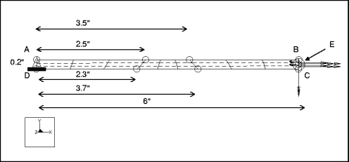
Element Type: | shell (3) | |
Units: | IPS | |
Dimensions: | length: 6 width: 0.2 thickness: 0.1 | |
Material Properties: | Mass Density: 0 Cost Per Unit Mass: 0 Young's Modulus: 1e7 | Poisson's Ratio: 0.3 Thermal Expansion: 0 Conductivity: 0 |
Constraints: | placed on edge A-D: fixed in all DOF | |
Loads: | Location/Magnitude: | Distribution: | Spatial Variation: |
extension | placed on edge B-C: FX = 1 | total load | uniform |
in_plane | placed on edge B-C: FY = 1 | total load | uniform |
out_plane | placed on edge B-C: FZ = 1 | total load | uniform |
twist | placed on point E: MX = 1 | total load | N/A |
Theory | Structure | % Difference | |
Tip Disp. in Direction of Load (l=extension, m=max_disp_x) | 3e-5 | 2.998e-5 | 0.08% |
Tip Disp. in Direction of Load (l=in_plane, m=max_disp_y) | 0.1081 | 0.1079 | 0.32% |
Tip Disp. in Direction of Load (l=out_plane, m=max_disp_z) | 0.4321 | .4311 | 0.23% |
Tip Disp. in Direction of Load (l=twist, m=max_rot_x) | 0.03408 1 | 0.03381 | 0.79% |
Convergence %: 0.7% on Local Disp and SE | Max P: 6 | No. Equations: 906 | |
Analysis Type: | Static |
Model Type: | 3D |
Comparison: | The MacNealHarder Accuracy Tests |
Reference: | MacNeal, R.H., and Harder, R.L. "A Proposed Standard Set of Problems to Test Finite Element Accuracy." Finite Elements in Analysis and Design I. Elsevier Science Publishers, 1985. |
Description: | A curved beam, spanning a 90  arc, is fixed at one end and free at the other. If the beam is subjected to in-plane and out-of-plane loads at the free end, find the tip displacement in the direction of the load for both cases. arc, is fixed at one end and free at the other. If the beam is subjected to in-plane and out-of-plane loads at the free end, find the tip displacement in the direction of the load for both cases. |
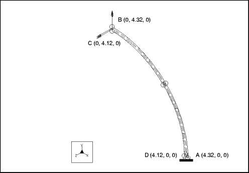
Element Type: | shell (2) | |
Units: | IPS | |
Dimensions: | outer radius: 4.32 inner radius: 4.12 thickness: 0.1 | |
Material Properties: | Mass Density: 0 Cost Per Unit Mass: 0 Young's Modulus: 1e7 | Poisson's Ratio: 0.25 Thermal Expansion: 0 Conductivity: 0 |
Constraints: | placed on edge A-D: fixed in all DOF | |
Loads: | Location/Magnitude: | Distribution: | Spatial Variation: |
in_plane | placed on edge B-C: FY = 1 | total load | uniform |
out_plane | placed on edge B-C: FZ = 1 | total load | uniform |
Theory | Structure | % Difference | |
Tip Displacement in Direction of Load (l=in_plane, m=tip_disp_y) | 0.08734 | 0.08833 | 1.13% |
Tip Displacement in Direction of Load (l=out_plane, m=tip_disp_z) | 0.5022 | 0.50057 | 0.32% |
Convergence %: 0.3% on Local Disp and SE | Max P: 6 | No. Equations: 234 | |
Analysis Type: | Static |
Model Type: | 3D |
Comparison: | The MacNealHarder Accuracy Tests |
Reference: | MacNeal, R.H., and Harder, R.L. "A Proposed Standard Set of Problems to Test Finite Element Accuracy." Finite Elements in Analysis and Design I. Elsevier Science Publishers, 1985. |
Description: | A flat plate is simply supported on all four edges. One quarter of the plate is modeled using symmetry. The plate is loaded with two different loads, including uniform pressure and a point load at the center. Find the displacement at the center of the plate. |

Element Type: | shell (2) | |
Units: | IPS | |
Dimensions: | length: 5 width: 1 thickness: 0.0001 | |
Material Properties: | Mass Density: 0 Cost Per Unit Mass: 0 Young's Modulus: 1.7472e7 | Poisson's Ratio: 0.3 Thermal Expansion: 0 Conductivity: 0 |
Constraints | Location | Degrees of Freedom |
placed on edges A-D, C-D: placed on edge A-B: placed on edge B-C: | fixed in TransX, TransY, and TransZ fixed in TransY, RotX, and RotZ fixed in TransX, RotY, and RotZ |
Loads: | Location/Magnitude: | Distribution: | Spatial Variation: |
pressure | placed on all shells: pressure = 1e4 | total load per unit area | uniform |
point | placed on B: FZ = 1e4 | N/A | N/A |
Theory | Structure | % Difference | |
Displacement @ Center (l=pressure, m=disp_z_cen) | –12.97 | –12.97 | 0.0% |
Displacement @ Center (l=point, m=disp_z_cen) | 16.96 | 16.81 | 0.88% |
Convergence %: 0.8% on Local Disp and SE | Max P: 9 | No. Equations: 438 | |
Analysis Type: | Static |
Model Type: | 3D |
Comparison: | The MacNealHarder Accuracy Tests |
Reference: | MacNeal, R.H., and Harder, R.L. "A Proposed Standard Set of Problems to Test Finite Element Accuracy." Finite Elements in Analysis and Design I. Elsevier Science Publishers, 1985. |
Description: | One quarter of a rectangular plate, clamped on four edges, is modeled using symmetry. The plate is loaded with two different loads, including uniform pressure and a point load at center. Find the displacement at the center of the plate. |
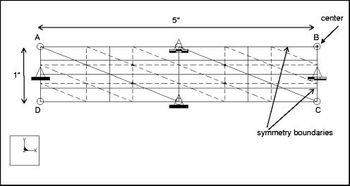
Element Type: | shell (2) | |
Units: | IPS | |
Dimensions: | length: 5 width: 1 thickness: 0.0001 | |
Material Properties: | Mass Density: 0 Cost Per Unit Mass: 0 Young's Modulus: 1.7472e7 | Poisson's Ratio: 0.3 Thermal Expansion: 0 Conductivity: 0 |
Constraints | Location | Degrees of Freedom |
placed on edges A-D, D-C: placed on edge A-B: placed on edge B-C: | fixed in all DOF fixed in TransY, RotX, and RotZ fixed in TransX, RotY, and RotZ |
Loads: | Location/Magnitude: | Distribution: | Spatial Variation: |
pressure | placed on all shells: pressure = 1e4 | per unit area | uniform |
point | placed on B: FZ = 1e4 | N/A | N/A |
Theory | Structure | % Difference | |
Displacement @ Center (l=pressure, m=measure1) | –2.56 | –2.604 | 1.71% |
Displacement @ Center (l=point, m=measure1) | 7.23 | 7.168 | 0.85% |
Convergence %: 1.3% on Local Disp and SE | Max P: 9 | No. Equations: 625 | |
Analysis Type: | Static |
Model Type: | 3D |
Comparison: | The MacNealHarder Accuracy Tests |
Reference: | MacNeal, R.H., and Harder, R.L. "A Proposed Standard Set of Problems to Test Finite Element Accuracy." Finite Elements in Analysis and Design I. Elsevier Science Publishers, 1985. |
Description: | One quarter of an open hemisphere is modeled with symmetry and loaded with alternating point loads at 90  intervals on the equator. Find the radial displacement at any load point. intervals on the equator. Find the radial displacement at any load point. |
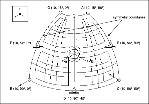
Element Type: | shell (4) | |
Units: | IPS | |
Dimensions: (using a one-quarter model) | radius: 10 arc span: 90o thickness: 0.04 | |
Material Properties: | Mass Density: 0 Cost Per Unit Mass: 0 Young's Modulus: 6.825e7 | Poisson's Ratio: 0.3 Thermal Expansion: 0 Conductivity: 0 |
Constraints | Location | Degrees of Freedom |
placed on curve A-C: placed on curve G-E: placed on point D | fixed in TransP, RotR, and RotT fixed in TransP, RotR, and RotT fixed in TransT |
Loads: | Location/Magnitude: | Distribution: | Spatial Variation |
placed on point C: FR = 1 placed on E: FR = 1 | N/A N/A | N/A N/A |
Theory | Structure | % Difference | |
Radial Displacement @ Load (m=disp_rad) | –0.0924 | –0.0933 | 0.97% |
Convergence %: 0.6% on Local Disp and SE | Max P: 9 | No. Equations: 1965 | |

Analysis Type: | Static |
Model Type: | 3D |
Comparison: | The MacNealHarder Accuracy Tests |
Reference: | MacNeal, R.H., and Harder, R.L. "A Proposed Standard Set of Problems to Test Finite Element Accuracy." Finite Elements in Analysis and Design I. Elsevier Science Publishers, 1985. |
Description: | A cantilever beam, twisted by 90  , is subjected to in-plane and out-of-plane loads at the free end. Find the tip displacement in the direction of the load for each case. , is subjected to in-plane and out-of-plane loads at the free end. Find the tip displacement in the direction of the load for each case. |

Element Type: | solid (2) | |
Units: | IPS | |
Dimensions: | length: 12 width: 1.1 thickness: 0.32 angle of twist 90o (from fixed to free end) | |
Material Properties: | Mass Density: 0 Cost Per Unit Mass: 0 Young's Modulus: 29e6 | Poisson's Ratio: 0.22 Thermal Expansion: 0 Conductivity: 0 |
Constraints: | placed on root surface: fixed in all DOF | |
Loads: | Location/Magnitude: | Distribution: | Spatial Variation: |
in_plane | placed on free end surface: FY = 1 | total load | uniform |
out_plane | placed on free end surface: FZ = 1 | total load | uniform |
Theory | Structure | % Difference | |
Tip Displacement in Direction of Load (l=in_plane, m=disp_tip_y1) | 0.005424 | 0.005428 | 0.73% |
Tip Displacement in Direction of Load (l=out_of_plane, m=disp_tip_z1) | 0.001754 | 0.001760 | 0.342% |
Convergence %: 0.8% on Local Disp and SE | Max P: 5 | No. Equations: 590 | |
Analysis Type: | Static |
Model Type: | 3D |
Comparison: | The MacNealHarder Accuracy Tests |
Reference: | MacNeal, R.H., and Harder, R.L. "A Proposed Standard Set of Problems to Test Finite Element Accuracy." Finite Elements in Analysis and Design I. Elsevier Science Publishers, 1985. |
Description: | A Scordelis-Lo roof is one-quarter of an arched roof modeled using symmetry and loaded uniformly. Find the vertical displacement at the midpoint of the straight side (of the whole roof). |
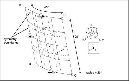
Element Type: | shell (1) | |
Units: | IPS | |
Dimensions: (using a one-quarter model) | length: 25 radius: 25 arc span: 40o thickness: 0.25 | |
Material Properties: | Mass Density: 0 Cost Per Unit Mass: 0 Young's Modulus: 4.32e8 | Poisson's Ratio: 0 Thermal Expansion: 0 Conductivity: 0 |
Constraints | Location | Degrees of Freedom |
(UCS) (UCS) (UCS) | placed on curve A-B: placed on curve A-D: placed on curve C-D | fixed in TransZ, RotR, and RotT fixed in TransT, RotZ, and RotR fixed in TransR and TransT |
Loads: | Location/Magnitude: | Distribution: | Spatial Variation: |
placed on face A-B-C-D: FZ = 90 | per unit area | uniform |
Theory | Structure | % Difference | |
Vertical Displacement @ Point B (m=disp_z_mid) | –0.3024 | –0.3008 | 0.53% |
Convergence %: 0.2% on Local Disp and SE | Max P: 7 | No. Equations: 148 | |
Analysis Type: | Static |
Model Type: | 2D Axisymmetric |
Reference: | NAFEMS, LSB1, No. IC 39 |
Description: | An axisymmetric cylinder and half-sphere vessel is loaded with uniform internal pressure. Find the hoop stress on the outer surface at point D. |

Element Type: | 2D shell (4) | |
Units: | MKS | |
Dimensions: | radius: 1 thickness: 0.025 | |
Material Properties: | Mass Density: 0.007 Cost Per Unit Mass: 0 Young's Modulus: 210000 | Poisson's Ratio: 0.3 Thermal Expansion: 0 Conductivity: 0 |
Constraints | Location | Degrees of Freedom |
constraint1 | placed on point A: placed on point E: | fixed in TransX and RotZ fixed in TransY |
Loads: | Location/Magnitude: | ||
load1 | placed on all 2D shell elements: internal pressure = 1 | ||
Theory | Structure1 | % Difference | |
Szz on outer surface | 38.5 | 38.62 | 0.3% |
Convergence %: 0.8% on Local Disp and SE | Max P: 7 | No. Equations: 72 | |
Analysis Type: | Static |
Model Type: | Plane Stress |
Reference: | NAFEMS, LSB1, No. IC 2 |
Description: | A tapered membrane has uniform acceleration in the global X direction. Find the direct stress Sxx at point B. |

Element Type: | 2D plate (2) | |
Units: | MKS | |
Dimensions: | thickness: 0.1 | |
Material Properties: | Mass Density: 0.007 Cost Per Unit Mass: 0 Young's Modulus: 210000 | Poisson's Ratio: 0.3 Thermal Expansion: 0 Conductivity: 0 |
Constraints: | Location | Degrees of Freedom |
constraint1 | placed on curves A-B, B-C: placed on point B: | fixed in TransX fixed in TransX, TransY |
Loads: | Location/Magnitude: |
load1 | Global acceleration: GX=9.81 |
Theory | Structure | % Difference | |
Stress XX at point B (m=measure1) | 0.247 | 0.247 | 0% |
Convergence %: 0.7% on Local Disp and SE | Max P: 7 | No. Equations: 248 | |
Analysis Type: | Static |
Model Type: | 3D |
Reference: | NAFEMS, LSB1, No. IC 29 |
Description: | A Z-section cantilevered plate is subjected to a torque at the free end by two uniformly distributed edge shears. Find the direct stress Sxx at the mid-plane of the plate. |
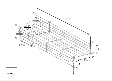
Element Type: | shell (6) | |
Units: | MKS | |
Dimensions: | length: 10 thickness: 0.1 | |
Material Properties: | Mass Density: 0.007 Cost Per Unit Mass: 0 Young's Modulus: 210000 | Poisson's Ratio: 0.3 Thermal Expansion: 0 Conductivity: 0 |
Constraints | Location | Degrees of Freedom |
constraint1 | placed on curves A-B, B-C, and C-D: | fixed in TransX, TransY, and TransZ |
Loads: | Location/Magnitude: | Distribution | Spatial Variation |
load1 | placed on curve E-F: FZ=0.6 placed on curve G-H: FZ=0.6 | total load total load | uniform uniform |
Theory | Structure1 | % Difference | |
Sxx at mid-surface at point M | –108.8 | –110.02 | 1.1% |
Convergence %: 0.4% on Local Disp and SE | Max P: 7 | No. Equations: 870 | |
Analysis Type: | Static |
Model Type: | 3D |
Reference: | NAFEMS, LSB1, No. IC 19 |
Description: | A cylindrical shell in 3D space is loaded with a uniform normal edge moment on one edge. Find the outer surface tangential stress at point E. |
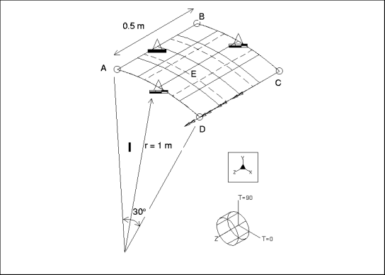
Element Type: | shell (1) | |
Units: | MKS | |
Dimensions: | radius: 1 thickness: 0.01 | |
Material Properties: | Mass Density: 0.007 Cost Per Unit Mass: 0 Young's Modulus: 210000 | Poisson's Ratio: 0.3 Thermal Expansion: 0 Conductivity: 0 |
Constraints | Location | Degrees of Freedom |
constraint1 | placed on curve A-B: placed on curves A-D and B-C: | fixed in all DOF fixed in TransZ, RotX, and RotY |
Loads: | Location/Magnitude: | Distribution | Spatial Variation |
load1 | placed on curve C-D: MZ=0.001 | force per unit length | uniform |
Theory | Structure1 | % Difference | |
Sxx on outer surface at point E | 60.0 | 59.6 | .67% |
Convergence %: 0.9% on Local Disp and SE | Max P: 5 | No. Equations: 66 | |
Analysis Type: | Static |
Model Type: | 3D |
Comparison: | Theory |
Reference: | Roark, R.J., and Young, W.C. Formulas for Stress and Strain. 5th Edition. NY: McGrawHill Book Co. 1982, p. 64. |
Description: | A cantilever beam is subjected to transverse loads in Y and Z and axial load in X . Find the deflection at the free end, the bending stress at the fixed end, and the axial stress along the beam. |
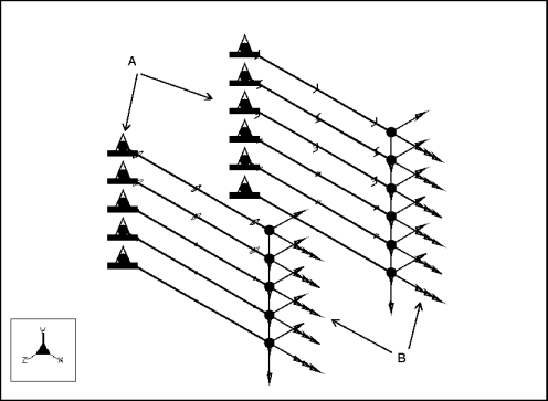
Element Type: | Square Beam | |
Units: | IPS | |
Dimensions: | a: 0.25 | |
Beam Properties: | Area: 0.0625 IYY: 0.000325521 Shear FY: 10001 CY: 0.125 | J: 0.000549316 IZZ: 0.000325521 Shear FZ: 10001 CZ: 0.125 |
Material Properties: | Mass Density: 0 Cost Per Unit Mass: 0 Young's Modulus: 3e7 | Poisson's Ratio: 0.3 Thermal Expansion: 0 Conductivity: 0 |
Constraints: | placed on point A: fixed in all DOF | |
Load: | Location: | Magnitude: |
axial | placed on point B | FX=100 |
transverse y | placed on point B | FY=100 |
transverse z | placed on point B | FZ=100 |
Load | Measure Name | Theory | Structure | % Difference |
Deflection at Tip: | ||||
axial | sq_d_x | 1.6e-3 | 1.6e-3 | 0% |
transverse y | sq_d_y | 9.216e1 | 9.216e1 | 0% |
transverse z | sq_d_z | 9.216e1 | 9.216e1 | 0% |
Stress: | ||||
axial | sq_s_ten | 1.6e3 | 1.6e3 | 0% |
transverse y | sq_s_bnd | 1.152003e6 | 1.15200e6 | 0% |
transverse z | sq_s_bnd | 1.152003e6 | 1.15200e6 | 0% |
Load | Lcl Disp & SE | Max P | No. Equations | |
Convergence: | ||||
axial | 0% | 2 | 264 | |
transverse y | 0% | 2 | 264 | |
transverse z | 0% | 2 | 264 | |
Element Type: | Rectangle Beam | |
Units: | IPS | |
Dimensions: | b: 1 d: 0.25 | |
Beam Properties: | Area: 0.25 IYY: 0.0208333 Shear FY: 10001 CY: 0.125 | J: 0.00438829 IZZ: 0.00130208 Shear FZ: 10001 CZ: 0.5 |
Material Properties: | Mass Density: 0 Cost Per Unit Mass: 0 Young's Modulus: 3e7 | Poisson's Ratio: 0.3 Thermal Expansion: 0 Conductivity: 0 |
Constraints: | placed on point A: fixed in all DOF | |
Load: | Location: | Magnitude: |
axial | placed on point B | FX=100 |
transverse y | placed on point B | FY=100 |
transverse z | placed on point B | FZ=100 |
Load | Measure Name | Theory | Structure | % Difference |
Deflection at Tip: | ||||
axial | rct_d_x | 4.0e-4 | 4.0e-4 | 0% |
transverse y | rct_d_y | 2.304e1 | 2.304e1 | 0% |
transverse z | rct_d_z | 1.44 | 1.44 | 0% |
Stress: | ||||
Load | Measure Name | Theory | Structure | % Difference |
axial | rct_s_ten | 4.0e2 | 4.0e2 | 0% |
transverse y | rct_s_bnd | 2.880e5 | 2.880e5 | 0% |
transverse z | rct_s_bnd | 7.200e4 | 7.200e4 | 0% |
Load | Lcl Disp & SE | Max P | No. Equations | |
Convergence: | ||||
axial | 0% | 2 | 264 | |
transverse y | 0% | 2 | 264 | |
transverse z | 0% | 2 | 264 | |
Element Type: | Hollow Rectangle Beam | |
Units: | IPS | |
Dimensions: | b: 1 bi: 0.875 d: 0.25 di: 0.125 | |
Beam Properties: | Area: 0.140625 IYY: 0.013855 Shear FY: 10001 CY: 0.125 | J: 0.00343323 IZZ: 0.00115967 Shear FZ: 10001 CZ: 0.5 |
Material Properties: | Mass Density: 0 Cost Per Unit Mass: 0 Young's Modulus: 3e7 | Poisson's Ratio: 0.3 Thermal Expansion: 0 Conductivity: 0 |
Constraints: | placed on point A: fixed in all DOF | |
Load: | Location: | Magnitude: |
axial | placed on point B | FX=100 |
transverse y | placed on point B | FY=100 |
transverse z | placed on point B | FZ=100 |
Load | Measure Name | Theory | Structure | % Difference |
Deflection at Tip: | ||||
axial | hrct_d_x | 7.112e-4 | 7.111e-4 | 0.02% |
transverse y | hrct_d_y | 2.5869e1 | 2.5876e1 | 0.027% |
transverse z | hrct_d_z | 2.1653 | 2.1677 | 0.10% |
Stress: | ||||
Load | Measure Name | Theory | Structure | % Difference |
axial | hrct_s_ten | 7.112e2 | 7.111e2 | 0.01% |
transverse y | hrct_s_bnd | 3.2337e5 | 3.2336e5 | 0.003% |
transverse z | hrct_s_bnd | 1.0826e5 | 1.0826e5 | 0% |
Load | Lcl Disp & SE | Max P | No. Equations | |
Convergence: | ||||
axial | 0% | 2 | 264 | |
transverse y | 0% | 2 | 264 | |
transverse z | 0% | 2 | 264 | |
Element Type: | Channel Beam | |
Units: | IPS | |
Dimensions: | b: 1 di: 1 t: 0.125 tw: 0.125 | |
Beam Properties: | Area: 0.375 IYY: 0.0369466 Shear FY: 10001 CY: 0.625 | J: 0.00179932 IZZ: 0.0898438 Shear FZ: 10001 CZ: 0.645833 |
Material Properties: | Mass Density: 0 Cost Per Unit Mass: 0 Young's Modulus: 3e7 | Poisson's Ratio: 0.3 Thermal Expansion: 0 Conductivity: 0 |
Constraints: | placed on point A: fixed in all DOF | |
Load: | Location: | Magnitude: |
axial | placed on point B | FX=100 |
transverse y | placed on point B | FY=100 |
transverse z | placed on point B | FZ=100 |
Load | Measure Name | Theory | Structure | % Difference |
Deflection at Tip: | ||||
axial | chnl_d_x | 2.6667e-4 | 6.061674e-04 | 0% |
transverse y | chnl_d_y | 3.339e-1 | -3.339e-1 | 0% |
transverse z | chnl_d_z | 8.1198e-1 | -8.1198e-1 | 0% |
Stress: | ||||
Load | Measure Name | Theory | Structure | % Difference |
axial | chnl_s_ten | 2.6667e2 | 2.6667e2 | 0% |
transverse y | chnl_s_bnd | 2.087e4 | 2.087e4 | 0% |
transverse z | chnl_s_bnd | 5.244e4 | 5.244e4 | 0% |
Convergence: | ||||
Load | Lcl Disp & SE | Max P | No. Equations | |
axial | 0% | 4 | 264 | |
transverse y | 0% | 4 | 264 | |
transverse z | 0% | 4 | 264 | |
Element Type: | I-Section Beam | |
Units: | IPS | |
Dimensions: | b: 1 di: 1 t: 0.125 tw: 0.125 | |
Beam Properties: | Area: 0.375 IYY: 0.0209961 Shear FY: 10001 CY: 0.625 | J: 0.00179932 IZZ: 0.0898438 Shear FZ: 10001 CZ: 0.5 |
Material Properties: | Mass Density: 0 Cost Per Unit Mass: 0 Young's Modulus: 3e7 | Poisson's Ratio: 0.3 Thermal Expansion: 0 Conductivity: 0 |
Constraints: | placed on point A: fixed in all DOF | |
Load: | Location: | Magnitude: |
axial | placed on point B | FX=100 |
transverse y | placed on point B | FY=100 |
transverse z | placed on point B | FZ=100 |
Load | Measure Name | Theory | Structure | % Difference |
Deflection at Tip: | ||||
axial | I_d_x | 2.6667e-4 | 2.6667e-4 | 0% |
transverse y | I_d_y | 3.3391e-1 | 3.3573e-1 | 0.54% |
transverse z | I_d_z | 1.4288 | 1.4296 | 0.05% |
Stress: | ||||
Load | Measure Name | Theory | Structure | % Difference |
axial | I_s_ten | 2.6667e2 | 2.6667e2 | 0% |
transverse y | I_s_bnd | 2.0870e4 | 2.0869e4 | 0.004% |
transverse z | I_s_bnd | 7.1442e4 | 7.14418e4 | 0.001% |
Load | Lcl Disp & SE | Max P | No. Equations | |
Convergence: | ||||
axial | 0% | 2 | 264 | |
transverse y | 0% | 2 | 264 | |
transverse z | 0% | 2 | 264 | |
Element Type: | L-Section Beam | |
Units: | IPS | |
Dimensions: | b: 1 d: 1 t: 0.125 tw: 0.125 | |
Beam Properties: | Area: 0.25 IYY: 0.0105794 Shear FY: 10001 CY: 0.789352 | J: 0.00119955 IZZ: 0.0423177 Shear FZ: 10001 CZ: 0.433047 |
Material Properties: | Mass Density: 0 Cost Per Unit Mass: 0 Young's Modulus: 3e7 | Poisson's Ratio: 0.3 Thermal Expansion: 0 Conductivity: 0 |
Constraints: | placed on point A: fixed in all DOF | |
Load: | Location: | Magnitude: |
axial | placed on point B | FX=100 |
transverse y | placed on point B | FY=100 |
transverse z | placed on point B | FZ=100 |
Load | Measure Name | Theory | Structure | % Difference |
Deflection at Tip: | ||||
axial | L_d_x | 4.0e-4 | 4.0e-4 | 0% |
transverse y | L_d_y | 7.0892e-1 | 7.1017e-1 | 0.17% |
transverse z | L_d_z | 2.8357 | 2.8369 | 0.04% |
Stress: | ||||
Load | Measure Name | Theory | Structure | % Difference |
axial | L_s_ten | 4e2 | 4e2 | 0% |
transverse y | L_s_ben | 5.5611e4 | 0 | — |
transverse z | L_s_ben | 1.228e5 | 0 | — |
Load | Lcl Disp & SE | Max P | No. Equations | |
Convergence: | ||||
axial | 0% | 2 | 264 | |
transverse y | 0% | 2 | 264 | |
transverse z | 0% | 2 | 264 | |
Element Type: | Diamond Beam | |
Units: | IPS | |
Dimensions: | b: 0.25 d: 0.25 | |
Beam Properties: | Area: 0.03125 IYY: 8.13802e5 Shear FY: 10001 CY: 0.125 | J: 0.000146484 IZZ: 8.13802e5 Shear FZ: 10001 CZ: 0.125 |
Material Properties: | Mass Density: 0 Cost Per Unit Mass: 0 Young's Modulus: 3e7 | Poisson's Ratio: 0.3 Thermal Expansion: 0 Conductivity: 0 |
Constraints: | placed on point A: fixed in all DOF | |
Load: | Location: | Magnitude: |
axial | placed on point B | FX=100 |
transverse y | placed on point B | FY=100 |
transverse z | placed on point B | FZ=100 |
Load | Measure Name | Theory | Structure | % Difference |
Deflection at Tip: | ||||
axial | dmnd_d_x | 3.2e-3 | 3.2e-3 | 0% |
transverse y | dmnd_d_y | 3.6864e2 | 3.6864e2 | 0% |
transverse z | dmnd_d_z | 3.6864e2 | 3.6864e2 | 0% |
Stress: | ||||
Load | Measure Name | Theory | Structure | % Difference |
axial | dmnd_s_ten | 3.2e3 | 3.2e3 | 0% |
transverse y | dmnd_s_bnd | 4.608e6 | 4.608e6 | 0% |
transverse z | dmnd_s_bnd | 4.608e6 | 4.608e6 | 0% |
Load | Lcl Disp & SE | Max P | No. Equations | |
Convergence: | ||||
axial | 0% | 2 | 264 | |
transverse y | 0% | 2 | 264 | |
transverse z | 0% | 2 | 264 | |
Element Type: | Solid Circle Beam | |
Units: | IPS | |
Dimensions: | r: 0.25 | |
Beam Properties: | Area: 0.19635 IYY: 0.00306796 Shear FY: 10001 CY: 0.25 | J: 0.00613592 IZZ: 0.00306796 Shear FZ: 10001 CZ: 0.25 |
Material Properties: | Mass Density: 0 Cost Per Unit Mass: 0 Young's Modulus: 3e7 | Poisson's Ratio: 0.3 Thermal Expansion: 0 Conductivity: 0 |
Constraints: | placed on point A: fixed in all DOF | |
Load: | Location: | Magnitude: |
axial | placed on point B | FX=100 |
transverse y | placed on point B | FY=100 |
transverse z | placed on point B | FZ=100 |
Load | Measure Name | Theory | Structure | % Difference |
Deflection at Tip: | ||||
axial | crcl_d_x | 5.093e-4 | 5.092e-4 | 0.019% |
transverse y | crcl_d_y | 9.77848 | 9.77995 | 0.015% |
transverse z | crcl_d_z | 9.77848 | 9.77995 | 0.015% |
Stress: | ||||
axial | crcl_s_ten | 5.093e2 | 5.092e2 | 0.019% |
transverse y | crcl_s_bnd | 2.44462e5 | 2.44462e5 | 0% |
transverse z | crcl_s_bnd | 2.44462e5 | 2.44462e5 | 0% |
Load | Lcl Disp & SE | Max P | No. Equations | |
Convergence: | ||||
axial | 0% | 2 | 264 | |
transverse y | 0% | 2 | 264 | |
transverse z | 0% | 2 | 264 | |
Element Type: | Hollow Circle Beam | |
Units: | IPS | |
Dimensions: | ri: 0.25 | |
Beam Properties: | Area: 0.147262 IYY: 0.00287621 Shear FY: 100001 CY: 0.25 | J: 0.00575243 IZZ: 0.00287621 Shear FZ: 10001 CZ: 0.25 |
Material Properties: | Mass Density: 0 Cost Per Unit Mass: 0 Young's Modulus: 3e7 | Poisson's Ratio: 0.3 Thermal Expansion: 0 Conductivity: 0 |
Constraints: | placed on point A: fixed in all DOF | |
Load: | Location: | Magnitude: |
axial | placed on point B | FX=100 |
transverse y | placed on point B | FY=100 |
transverse z | placed on point B | FZ=100 |
Load | Measure Name | Theory | Structure | % Difference |
Deflection at Tip: | ||||
axial | hcr_d_x | 6.7906e-4 | 6.7906e-4 | 0% |
transverse y | hcr_d_y | 1.04304e1 | 1.04331e1 | 0.025% |
transverse z | hcr_d_z | 1.04304e1 | 1.04332e1 | 0.026% |
Stress: | ||||
axial | hcr_s_ten | 6.7906e2 | 6.7906e2 | 0% |
transverse y | hcr_s_bnd | 2.6076e5 | 2.6075e5 | 0.003% |
transverse z | hcr_s_bnd | 2.6076e5 | 2.6076e5 | — |
Load | Lcl Disp & SE | Max P | No. Equations | |
Convergence: | ||||
axial | 0% | 2 | 264 | |
transverse y | 0% | 2 | 264 | |
transverse z | 0% | 2 | 264 | |
Element Type: | Ellipse Beam | |
Units: | IPS | |
Dimensions: | a: 1 b: 0.25 | |
Beam Properties: | Area: 0.785398 IYY: 0.19635 Shear FY: 10001 CY: 0.25 | J: 0.0461999 IZZ: 0.0122718 Shear FZ: 10001 CZ: 1 |
Material Properties: | Mass Density: 0 Cost Per Unit Mass: 0 Young's Modulus: 3e7 | Poisson's Ratio: 0.3 Thermal Expansion: 0 Conductivity: 0 |
Constraints: | placed on point A: fixed in all DOF | |
Load: | Location: | Magnitude: |
axial | placed on point B | FX=100 |
transverse y | placed on point B | FY=100 |
transverse z | placed on point B | FZ=100 |
Load | Measure Name | Theory | Structure | % Difference |
Deflection at Tip: | ||||
axial | elps_d_x | 1.2732e-4 | 1.2732e-4 | 0% |
transverse y | elps_d_y | 2.4446 | 2.4445 | 0.004% |
transverse z | elps_d_z | 1.527887e-1 | 1.531516e-1 | 0.23% |
Stress: | ||||
axial | elps_s_ten | 1.273239e2 | 1.27324e2 | 0% |
transverse y | elps_s_bnd | 6.11155e4 | 6.111550e4 | 0% |
transverse z | elps_s_bnd | 1.527887e4 | 1.527887e+04 | 0% |
Load | Lcl Disp & SE | Max P | No. Equations | |
Convergence: | ||||
axial | 0% | 2 | 264 | |
transverse y | 0% | 2 | 264 | |
transverse z | 0% | 2 | 264 | |
Element Type: | Hollow Ellipse Beam | |
Units: | IPS | |
Dimensions: | a: 1 b: 0.25 ai: 0.875 | |
Beam Properties: | Area: 0.184078 IYY: 0.081253 Shear FY: 10001 CY: 0.25 | J: 0.0191184 IZZ: 0.00507832 Shear FZ: 10001 CZ: 1 |
Material Properties: | Mass Density: 0 Cost Per Unit Mass: 0 Young's Modulus: 3e7 | Poisson's Ratio: 0.3 Thermal Expansion: 0 Conductivity: 0 |
Constraints: | placed on point A: fixed in all DOF | |
Load: | Location: | Magnitude: |
axial | placed on point B | FX=100 |
transverse y | placed on point B | FY=100 |
transverse z | placed on point B | FZ=100 |
Load | Measure Name | Theory | Structure | % Difference |
Deflection at Tip: | ||||
axial | hel_d_x | 5.4325e-4 | 5.4324e-4 | 0.0018% |
transverse y | hel_d_y | 5.9075 | 5.9091 | 0.45% |
transverse z | hel_d_z | 3.6922e-1 | 3.7091e-1 | 0.027% |
Stress: | ||||
axial | hel_s_ten | 5.4325e2 | 5.4324e2 | 0.0018% |
transverse y | hel_s_bnd | 1.4769e5 | 1.4768e5 | 0.0027% |
transverse z | hel_s_bnd | 3.6922e4 | 3.6921e4 | 0.0067% |
Load | Lcl Disp & SE | Max P | No. Equations | |
Convergence: | ||||
axial | 0% | 2 | 264 | |
transverse y | 0% | 2 | 264 | |
transverse z | 0% | 2 | 264 | |
Analysis Type: | Static |
Model Type: | 3D |
Reference: | Roark, R.J., and Young, W.C. Formulas for Stress and Strain. NY: McGraw-Hill Book Co., 5th edition, Table 32, Case 1. |
Description: | A thick-walled cylinder subjected to an internal pressure is free to expand in all directions. Obtain maximum radial and circumferential stresses. |
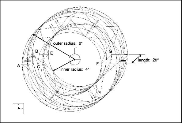
Element Type: | tets (133) | |
Units: | IPS | |
Dimensions: | length: 20 Ro: 6 Ri: 4 | |
Material Properties: | Mass Density: 0.0002614 Cost Per Unit Mass: 0 Young's Modulus: 1.06e7 | Poisson's Ratio: 0.33 Thermal Expansion: 1.25e05 Conductivity: 9.254 |
Constraints | Location | Degrees of Freedom |
constraint1 | placed on point A: placed on point B: placed on point D: | fixed in TransX, TransY, and TransZ fixed in TransY fixed in TransY and TransZ |
Loads: | Location/Magnitude: | Distribution | Spatial Variation |
pressure | placed on all internal surfaces: pressure = 1000 | total load/unit area | uniform |
Theory | Structure | % Difference | |
 yy along edges C-E & F-G yy along edges C-E & F-G | 2600 | 2603.7325 | 0.14% |
 xx along edges C-E & F-G xx along edges C-E & F-G | 1000 | 999.1724 | 0.08% |
Multi-Pass Convergence %: The analysis converged to within 1% on measures. | Max P: 6 | No. Equations: 1875 | |
Analysis Type: | Static |
Model Type: | 3D Cyclic Symmetric |
Reference: | Roark, R.J., and Young, W.C. Formulas for Stress and Strain. NY: McGraw-Hill Book Co., 5th edition, Table 29, Case 3c. |
Description: | A thin-walled half-spherical vessel is subjected to its own weight (gravity load). Obtain the hoop stress at points A and B. |

Element Type: | shells (3) | |
Units: | IPS | |
Dimensions: | R: 10 | |
Material Properties: | Mass Density: 0.0002588 Cost Per Unit Mass: 0 Young's Modulus: 1.0e7 | Poisson's Ratio: 0.3 Thermal Expansion: 0 Conductivity: 0 |
Constraints | Location | Degrees of Freedom |
constraint1 | Edges @  = 0 & = 0 &  = 90: = 90:Edge @ z = 0: Placed on point C @ r = 10,  = 0, z = 0: = 0, z = 0: | cyclical symmetry fixed in TransZ fixed in TransR, TransT, and TransZ |
Load: | Direction: | Magnitude: |
gravity | x y z | 0.0 386.4 0.0 |
Theory | Structure | % Difference | |
 zz at point A: zz at point A: | 1 | 0.987 | 1.3% |
 tt at point B: tt at point B: | -1 | -0.982 | 1.8% |
Multi-Pass Adaptive Convergence %: The analysis converged to within 4.9% on Local Displacement and Element Strain Energy. It converged to 1.7% on Global RMS Stress. | Max P: 9 | No. Equations: 773 | |
Analysis Type: | Static with Orthotropic Material Properties |
Model Type: | 3D |
Comparison: | Theory |
Reference: | Noor, A.K. and Mathers, M.D., "Shear-Flexible Finite-Element Models of Laminated Composite Plates and Shells." NASA TN D-8044; Langley Research Center, Hampton, Va. Dec. 1975. |
Description: | Determine maximum resultant bending moment and transverse deformation in a clamped, nine-layered, orthotropic square plate. |

Element Type: | shell (4) | ||
Units: | IPS | ||
Dimensions: | length: 2.5 width: 2.5 thickness: 0.5 | ||
Shell Properties: | |||
Extensional Stiffness | A11=10.266 | A12=0.1252 | A16=0 |
A22=10.266 | A26=0 | ||
A66=0.3 | |||
ExtensionalBending Coupling Stiffness | B11=0 | B12=0 | B16=0 |
B22=0 | B26=0 | ||
B66=0 | |||
Bending Stiffness | D11=0.25965 | D12=0.0026082 | D16=0 |
D22=0.1681 | D26=0 | ||
D66=0.00625 | |||
Transverse Shear Stiffnesses | A55=0.275004 | A45=0 | A44=0.275004 |
Mass per Unit Area | 7.2915e5 | ||
Rotary Inertia per Unit Area | 1.5191e5 | ||
Thermal Resultant Coefficients: | |||
Force | N11=0 | N22=0 | N12=0 |
Moment | M11=0 | M22=0 | M12=0 |
Stress Recovery Locations | CZ | Ply Orientation (Degrees) | Material |
Location Reported for "Top" in Results | 0.25 | 0 | trniso1 |
Location Reported for "Bottom" in Results | 0.25 | 0 | trniso1 |
Material Properties: | |||
Mass Density: 0.00014583 | Cost Per Unit Mass: 0 | ||
Young's Moduli | E1=4e1 | E2=1 | E3=1 |
Poisson's Ratio | Nu21=0.25 | Nu31=0.25 | Nu32=0 |
Shear Moduli | G21=0.6 | G31=0.6 | G32= E2/[2*(1+Nu32)] |
Coefficients of Thermal Expansion | a1=0 | a2=0 | a3=0 |
Constraints: | symmetry constraints on edges B-C and C-D clamped on edges A-B and A-D | ||
Loads: | uniform pressure load over the entire surface = 1 | ||
Theory | Structure | % Difference | |
Displacement | 11.596 | 11.84151 | 2.11% |
Bending Moment 1 | 1.4094 | 1.41307 | 0.26% |
Convergence %: 1.1% on local displacement and element strain energy and 2.2 % on global RMS stress. | Max P: 3 | No. Equations: 76 | |