|
Analysis Type:
|
2D Contact
|
|
Model Type:
|
Plane Strain
|
|
Comparison:
|
Theory
|
|
Reference:
|
Roark, R.J. and Young, W. Formula for Stress and Strain. NY; McGraw-Hill Co. 1982. p. 517.
|
|
Description:
|
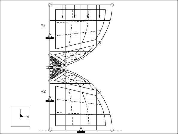
A half model of two cylinders of unit depth in contact. Modeled using 2D contact. Determine the maximum stress and contact area.
|

Element Type: | 2D solid | |
Units: | IPS | |
Dimensions: | R1: 1 R2: 1 | |
Material Properties: | Mass Density: 0 Cost Per Unit Mass: 0 Young's Modulus: 1e6 | Poisson's Ratio: 0.3 Thermal Expansion: 0 Conductivity: 0 |
Constraints: | fixed in all but y on vertical edges; fixed in all but x on bottom edge | |
Loads: | -1000 on top element edges (symmetry): Total Load=-2000 | |
Theory | Structure | % Difference | |
Contact Area | 0.0481 | 0.0481 | 0% |
Maximum Stress (m=contact_max_press) | 26450 | 26353.88 | 0.363% |
Convergence %: 0.8 % on Contact Area and Contact Pressure | Max P: 9 | No. Equations: 397 | |
Analysis Type: | 3D Contact |
Model Type: | 3D |
Comparison: | Theory |
Reference: | Roark, R.J. and Young, W. Formula for Stress and Strain. NY; McGraw-Hill Co. 1982. p. 517. |
Description: | A quarter section of two hemispheres in contact. Determine the maximum stress and contact area. |

Element Type: | 2D solid | |
Units: | IPS | |
Dimensions: | R1: 2 R2: 3 | |
Material Properties: | Mass Density: 1 Cost Per Unit Mass: 1 Young's Modulus: 1e7 | Poisson's Ratio: 0.3 Thermal Expansion: 1 Conductivity: 1 |
Constraints: | fixed in all but y on xz face; fixed in all but x on yz face; fixed on bottom edge | |
Loads: | -25000 on top element faces (symmetry): Total Load=-100000 | |
Theory | Structure | % Difference | |
Contact Area | 0.0507 | 0.0481 | 7.692% |
Maximum Stress (m=contact_max_pres) | 740285 | 742075.3 | 0.241% |
Convergence %: 1.6 % on measure convergence | Max P: 9 | No. Equations: 6192 | |
Analysis Type: | 2D contact |
Model Type: | 2D Plane Strain |
Comparison: | NAFEMS Benchmark |
Reference: | Benchmark tests for finite element modelling of contact, gap and sliding, Ref:- R0081, Issue: 1, CGS - 7, PP 53. |
Description: | The problem consists of a simple 2D model with finite friction subjected to prescribed displacement. |

Element Type: | 2D solid | |
Units: | mmNs | |
Dimensions: | R: 500 mm | |
Material Properties: | Mass Density: 7850 kg/m^3 Young's Modulus: 210 GPa | Poisson's Ratio: 0.3 |
Constraints: | The steel ring is fixed along X- axis. | |
Loads: | G = 2443 N Prescribed displacement x= 785 mm on bottom edge of the plate | |
Coefficient of Friction | μ=1.0 | |
NAFEMS | Structure | % Difference | |
Rotation in the ring in degree (m = rotation_ring) | 90 | 89.9 | 0.1 % |
Analysis Type: | 2D contact |
Model Type: | 2D Axisymmetric |
Comparison: | NAFEMS Benchmark |
Reference: | Benchmark tests for finite element modelling of contact, gap and sliding, Ref:- R0081, Issue: 1, CGS - 10, PP 61. |
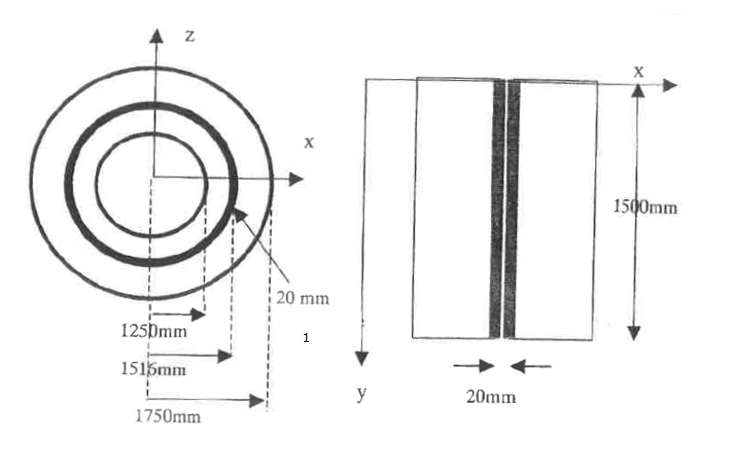
Description: | The problem consists of a simple 2D contact problem with 20 mm interference. Average contact pressure is computed. |

Element Type: | 2D Solid | |
Units: | mmNs | |
Dimensions: | As shown in the figure above | |
Material Properties: | Mass Density: 0 Young's Modulus: 206E9 N/m^2 | Poisson's Ratio: 0.0 |
Constraints: | The top and bottom of the two cylinders are constraint in the vertical direction. | |
Loads: | A dummy load is applied on extreme left edge. | |
NAFEMS | Structure | % Difference | |
Contact Pressure in N/m^2 (m = pressure_avg) | 2.275E8 | 2.346E8 | 3 % |
Analysis Type: | 2D contact |
Model Type: | 2D Axisymmetric |
Comparison: | NAFEMS Benchmark |
Reference: | Benchmark tests for finite element modelling of contact, gap and sliding, Ref:- R0081, Issue: 1, CGS - 4, PP 47. |
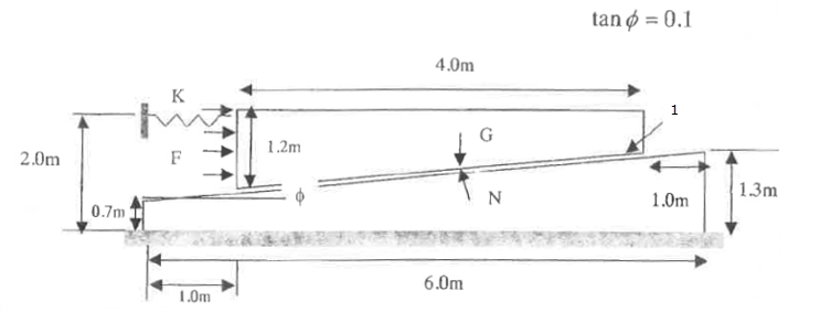
Description: | The problem consists of a simple 2D model with finite friction. |

Element Type: | 2D Solid | |
Units: | MKS | |
Dimensions: | As shown in the figure above | |
Material Properties: | Mass Density: 0 Young's Modulus: 206 GPa | Poisson's Ratio: 0.3 |
Constraints: | The bottom of the foundation is constrained in all directions. The left side of the wedge is connected to 9 linear springs (stiffness 98 N/m) in the horizontal direction. The other end of the springs are constrained in all directions. | |
Loads: | F = 1500 N G = 3058 N | |
Coefficient of Friction | μ= 0.1 | |
NAFEMS | Structure | % Difference | |
Horizontal Displacement (m = displacement_x) | 1.0 | 1.0 | 0 % |