Updating Drawings
In Creo, the 3D model and the drawing that references the model are associative. That means that changes you make in the 3D model appear in the drawing, and that changes you make in the drawing appear in the 3D model.
This exercise includes the following tasks:
Change the 3D model
In this task, you will make a few changes to a 3D model so that you can view the changes later in the drawing.
1. In Creo Parametric, set the working directory to <downloaded files location>, and open sp155051rh.prt.
2. To set the model view, click
 Saved Orientations
 on the in-graphics toolbar, and select
VIEW 1.
3. To disable all datum display filters, click
 Datum Display Filters
 on the in-graphics toolbar, and clear all the check boxes.
4. Click the Flexible Modeling tab.
5. To change the radius of a cylinder:
a. In the
Transform group, click
 Modify Analytic
. The
Modify Analytic Surface tab opens.
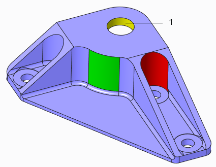
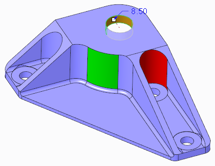
b. In the top hole, select the yellow cylindrical surface.
1. Yellow surface
c. In the Radius box, type 10.
d. Click

. The radius changes, and the Modify Analytic Surface 1 feature appears in the Model Tree.
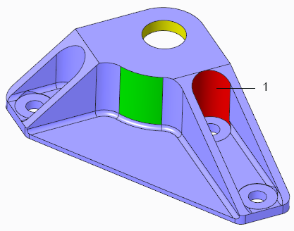
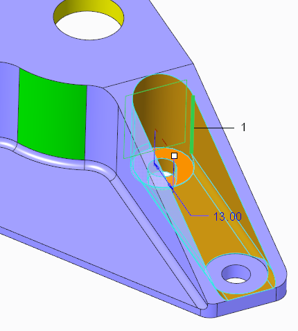
6. To edit a cut:
a. Select the red cylindrical surface.
1. Red surface
b. To select all the surfaces that form the cut, in the
Shape Surface Selection group, click
 Cut
Cut.
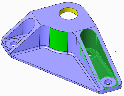
c. To add to the selection, hold down the CTRL key while you select the hole inside the selected area that is closest to the center of the model.
1. Hole
d. To select all the surfaces that form the hole, in the
Shape Surface Selection group, click
Cut.
e. In the
Transform group, click the arrow under
Move, and click
 Move by Dimension
.
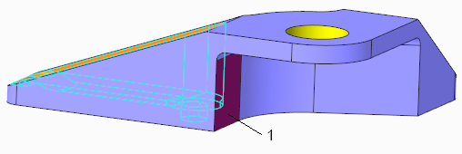
f. To view the back of the model, click
Saved Orientations, and select
VIEW 2.
g. To define the first reference for the move, select the purple surface on the back of the model.
1. Purple surface
h. To view the front of the model, click
Saved Orientations, and select
VIEW 1.
i. To define the second reference for the move, hold down the CTRL key while you select one of the vertical line in the selected area.
1. Vertical line
j. In the graphics window or on the Dimensions tab, edit the dimension value to 24.
k. Click
. The selected geometry moves. The Move 1 feature appears in the Model Tree.
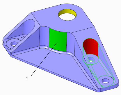
7. To change the radius of a surface:
a. Select VIEW 1 if it is not already selected.
b. Select the green cylindrical surface in the middle of the model.
c. In the
Transform group, click
Modify Analytic. The
Modify Analytic Surface tab opens.
d. Edit the Radius value to 35.
e. Click
. The Modify Analytic Surface 2 feature appears in the Model Tree.
View changes to the 3D model in the drawing
In this task, you observe how the changes you make in a 3D model using Creo Flexible Modeling are propagated to the drawing that references the model.
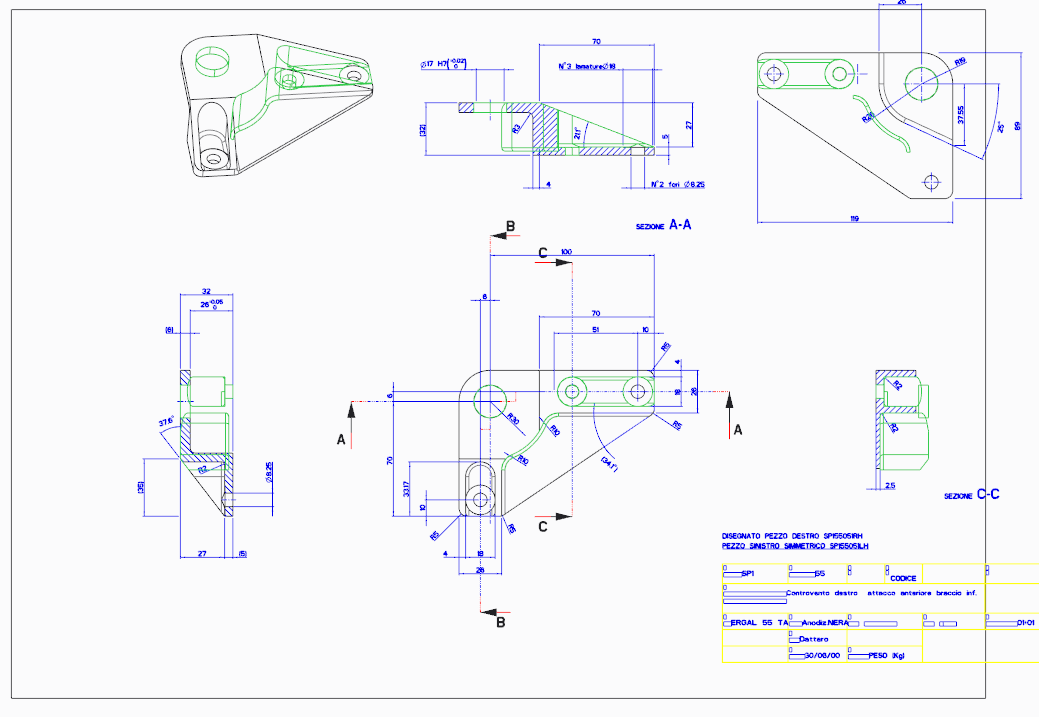
1. Open the drawing sp155051rh.drw. The drawing opens, with the Flexible Modeling features that you created highlighted in green.
A warning message appears stating that Flexible Modeling features have been detected, that some of the annotations might be outdated, and they should be reviewed and updated.
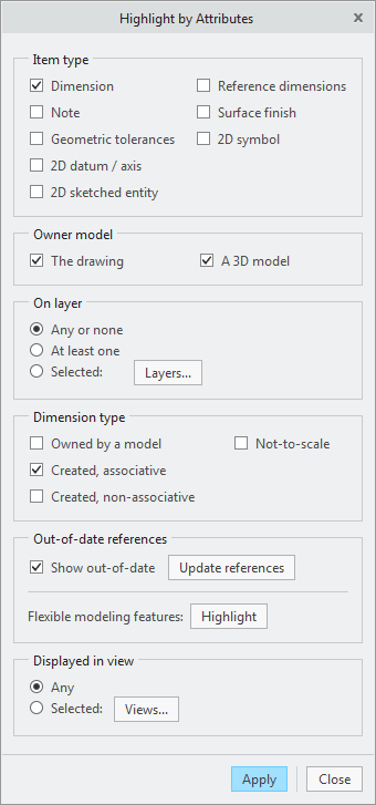
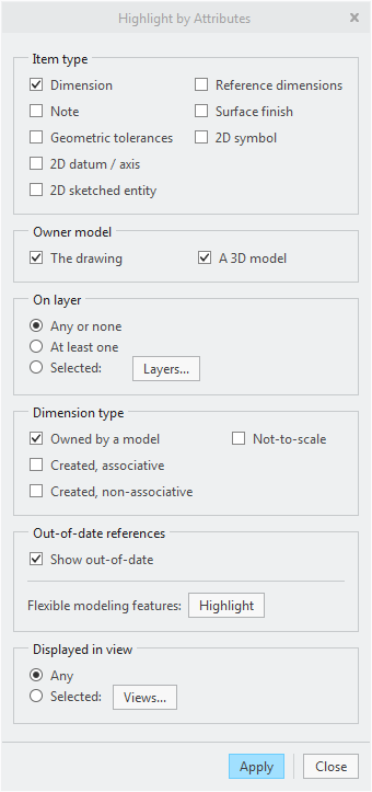
2. Read the warning and click Review. The Highlight by Attributes dialog box opens.
3. To redraw the current view, on the in-graphics toolbar, click
 Repaint
. The drawing is updated, and the highlighting disappears.
4. To highlight in the drawing the Flexible Modeling changes that you made previously in the model, in the Highlight by Attributes dialog box, next to Flexible modeling features, click Highlight.
5. In the Highlight by Attributes dialog box, under Dimension type:
a. Clear the Owned by a model check box.
b. Clear the Created, non-associative check box.
c. Click Apply.
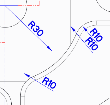
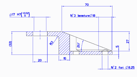
6. Zoom in on the bottom middle drawing. The dimensions where changes were made in the 3D model are now highlighted.
7. Observe the highlighted dimensions while you click Update references. The updated references become highlighted. Some of the references have been reassigned.
8. In the Highlight by Attributes dialog box:
a. Select the Owned by a model check box.
b. Clear the Created, associative check box.
c. Click Apply.
d. Close the Highlight by Attributes dialog box.
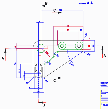
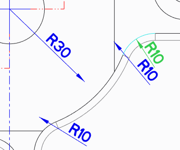
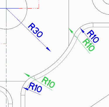
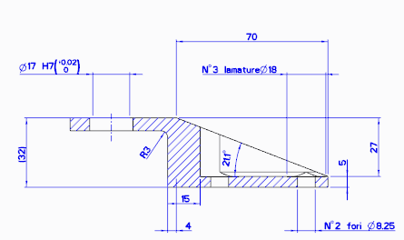
The R10 dimensioning is out of date because the radii of the model have been updated using Flexible Modeling. The references in the drawing are now outdated, and the R10 dimensioning is not pointing to any references.
Update the drawing—references
In this task, you update the dimensioning in your drawing to show the changes that you made in the 3D model using Creo Flexible Modeling. You will continue from where you left off in the previous task. The R10 dimensions are out of date, and you will update them to the changed references.
1. In the drawing, click the Annotate tab.
2. In the
Annotations group, click
 Dimension
. The
Select References dialog box opens.
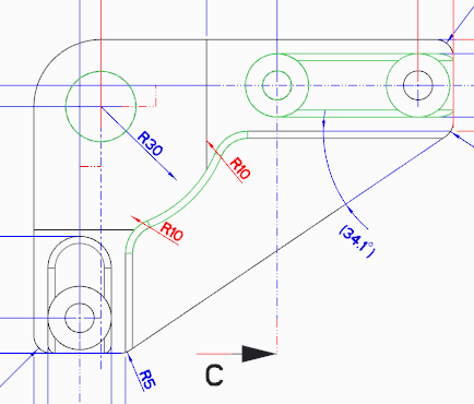
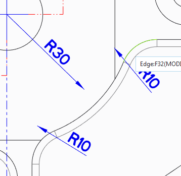
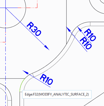
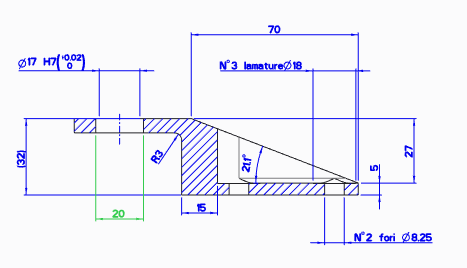
3. Point over the rounded edge where one of the R10 arrows should be, until the line highlights.
4. Click the highlighted edge to select the location where the tip of the dimension arrow should be. A new dimension appears in gray.
5. Move the cursor around and observe what happens to the dimensioning.
6. Middle-click to place the dimension. The dimension is highlighted.
7. Click the dimension to remove the highlighting.
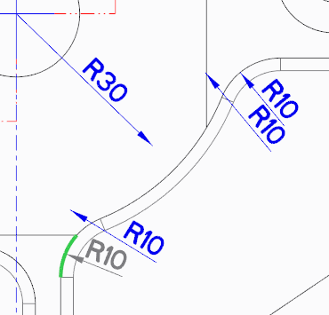
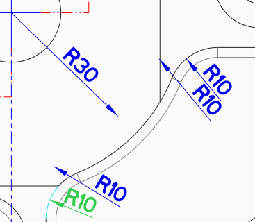
8. Repeat the steps for the second R10 dimension:
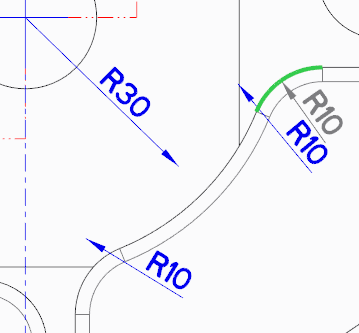
a. Point over the round where the second R10 arrow should be, until the line highlights.
b. Click the light green edge to select the location for the tip of the dimension arrow.
c. Middle-click to place the dimension.
d. Click the dimension to remove the highlighting.
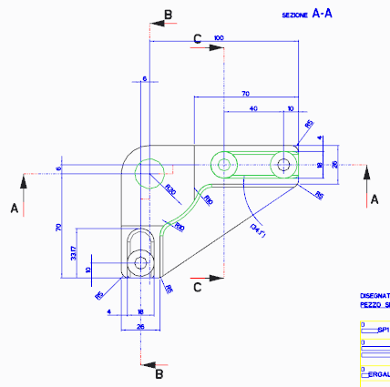
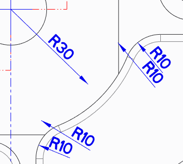
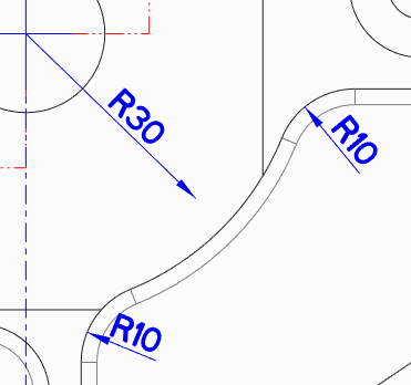
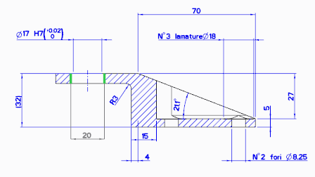
9. Close the Select References dialog box. Now the R10 dimensions are pointing to updated references.
10. To remove the outdated R10 dimensions:
a. Select one of the outdated R10 dimensions, and then hold down the CTRL key while you select the second outdated R10 dimension.
b. Right-click anywhere in the graphics window, and choose
 Delete
 from the shortcut menu. The outdated dimensions disappear.
Update the drawing—dimensions
In this task, you update dimension that are outdated in the drawing.
1. Click the Review tab.
2. In the
Query group, click
 Highlight by Attributes
. The
Highlight by Attributes dialog box opens.
3. In the Highlight by Attributes dialog box:
a. Select the Owned by a model check box.
b. Clear the Created, associative check box.
c. Clear the Created, non-associative check box.
d. Click Apply.
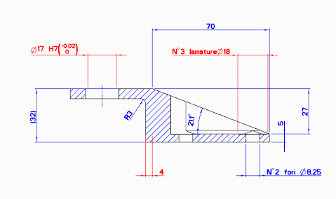
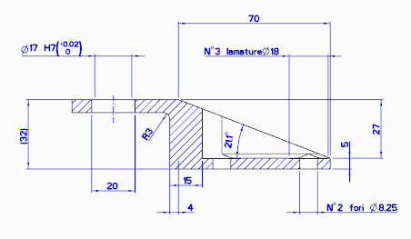
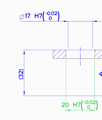
In the top middle image, the dimensioning is outdated.
4. Click the Annotate tab.
5. In the
Annotations group, click
Dimension. The
Select References dialog box opens.
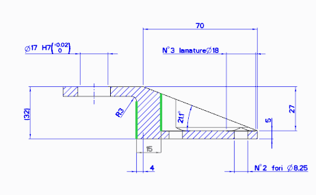
6. Select the first vertical line in the middle of the drawing, and then hold down the CTRL key while you select the second vertical line.
7. Middle-click to place the dimension.
8. Click to deselect the dimension.
9. Repeat the steps for the hole dimension in the upper left:
a. Select the first vertical line, and then hold down the CTRL key while you select the second vertical line.
b. Middle-click to place the dimension.
c. Click to deselect the dimension. The dimension turns blue.
10. Close the Select References dialog box. Now the dimensions are updated.
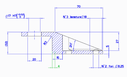
11. To remove the outdated dimension:
a. Select the outdated dimension with the value of 4.
b. Right-click anywhere in the graphics window, and choose
Delete from the shortcut menu. The outdated dimension disappear.
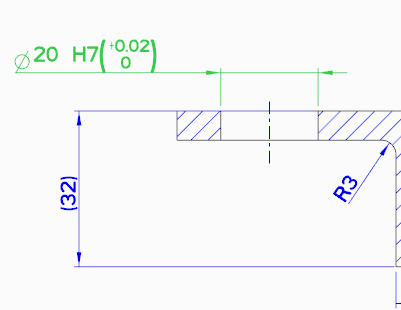
Set the dimension properties
In this task, you set the dimension properties.
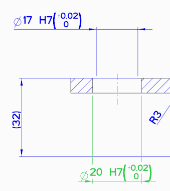
1. Click the hole dimension with the value of 20. The Dimension tab opens.
2. On the Dimension tab, in the Tolerance group:
a. Click the arrow under
 Tolerance
, and select
Plus-Minus.
b. Next to

tolerance table, select
Hole.
c. Next to

table name, select the letter
H, and then select the number
7. The changes are added to the drawing.
3. To define the dimension symbol, in the Dimension Text group:
a. Click
 Dimension Text
. A panel opens.
b. Click the

diameter symbol.
c. Click
Dimension Text again to close the panel.
4. To flip the direction of the arrows:
a. In the
Display group, click
 Display
. A panel opens.
b. Next to Arrow Direction, click Flip.
c. Click
Display again to close the panel.
5. Delete the old dimension with a value of 17.
6. Drag the new dimension to the position of the old dimension.
Observe the association between the 3D model and the drawing
In this task, you see how changes you make in the 3D model appear automatically in the drawing that references the model.
1. Make a change in the 3D model:
a. To return to the 3D model, on the Quick Access toolbar at the top of the drawing, click the arrow next to
 Windows
, and select
sp155051rh.prt.
b. In the Model Tree, right-click
Modify Analytic Surface 1, and choose

Edit Definition from the shortcut menu. The
Modify Analytic Surface tab opens.
c. Edit the
Radius to
8.5, and click
.
2. To return to the drawing, on the Quick Access toolbar, click the arrow next to
Windows, and select
sp155051rh.drw. Notice how the radius dimensioning updates automatically.