Removing Features
In this exercise, you will remove features from a pipe ventilator model. You will remove small geometric features, holes, and areas that increase the complexity of the mesh. Simplifying the model in this way increases the speed of analysis and simulation.
This exercise includes the following tasks:
Remove holes from the engine block
In this task, you use geometry rules selection to select multiple holes, and then you remove the holes from the model.
1. In Creo Parametric, set the working directory to <downloaded files location>, and open rohrventilator.prt.
2. To disable all datum display filters, click
 Datum Display Filters
 on the in-graphics toolbar, and clear all the check boxes.
3. To set the model view, click
 Saved Orientations
 on the in-graphics toolbar, and select
VIEW 1.
4. Click the Flexible Modeling tab.
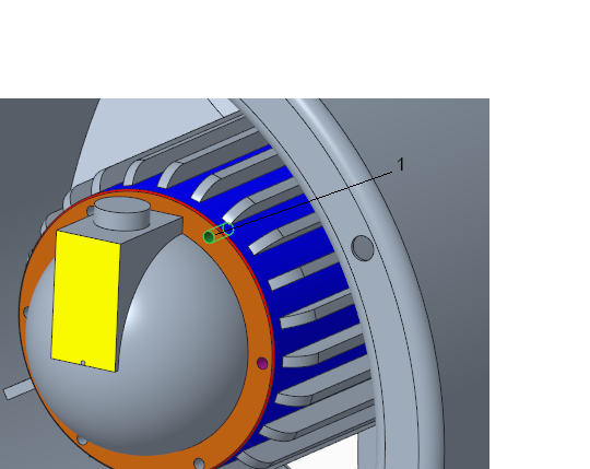
5. In the graphics window, select the cylindrical surface inside a hole on the inner ring-shaped surface.
1. Surface inside the hole
6. In the
Shape Surface Selection group, click
 Geometry Rules
, or right-click in the graphics window next to the model and select
Geometry Rule Surfaces. The
Geometry Rules dialog box opens.
7. To select all the holes with the same radius as the selected hole, select the Equal radius check box. Notice that additional holes become selected.
8. Click
OK. The
Geometry Rules dialog box closes, and the holes with the same radius are selected.
9. To remove the selected holes, in the
Edit Features group, click
 Remove
. The
Remove Surface tab opens.
10. Click

. The holes are removed. The Remove 1 feature appears in the Model Tree.
Remove a boss
In this task, you select a seed surface, use shape surface selection to select the boss, and remove the boss.
1. Click
Saved Orientations on the in-graphics toolbar, and select
VIEW 1.
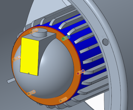
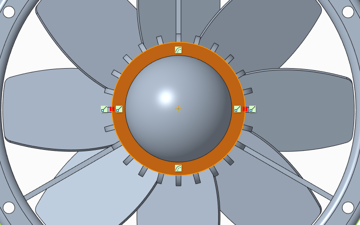
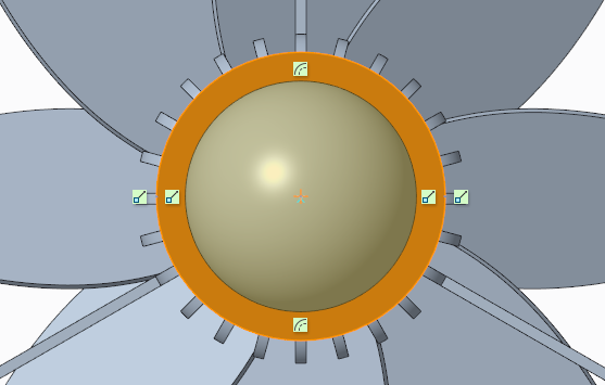
2. In the graphics window, select the yellow surface in the middle of the part. This is the seed surface for your selection.
3. To select the entire boss of which the selected surface is a part, along with smaller surfaces that intersect it, in the
Shape Surface Selection group, click
 Bosses
. The entire boss is selected.
4. To remove the selected boss, click
Remove. The
Remove Surface tab opens.
5. Click
. The boss is removed. The Remove 2 feature appears in the Model Tree.
Remove a chamfer
In this task, you remove a chamfer.
1. Click
Saved Orientations on the in-graphics toolbar, and select
VIEW 1.
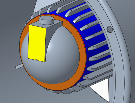
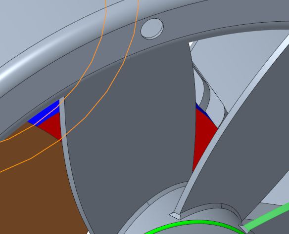
2. Select part of the red chamfer surface that is outside the orange ring-shaped surface.
1. Chamfer
3. In the
Transform group, click
 Edit Chamfer
. The
Edit Chamfer tab opens. The entire chamfer is selected.
4. On the Edit Chamfer tab, select the Remove chamfer check box.
5. Click
. The chamfer is removed. The Edit Chamfer 1 feature appears in the Model Tree.
Remove ribs from the ventilator
In this task, you remove ribs. Usually you would select the ribs to remove using pattern recognition, but in this case, not all the ribs are equal. Instead of selecting the ribs, the method you will use is to create an extruded cylinder that covers the ribs, and then reduce the dimension of the cylinder to the original value of the cylinder on which the ribs lie. This has the affect of removing the ribs.
1. Click
Saved Orientations on the in-graphics toolbar, and select
VIEW 1.
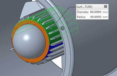
2. To measure the diameter of the blue cylindrical surface on which the ribs are located:
a. Click the Analysis tab.
b. Click
Measure >
 Diameter
. The
Measure dialog box opens
c. Click the blue cylindrical surface. A measure panel appears on the surface. Note that the radius is 40 mm.
d. Close the Measure dialog box.
3. Click the Model tab.
4. Click
 Extrude
. The
Extrude tab opens, with the
Sketch collector active on the
Placement tab.
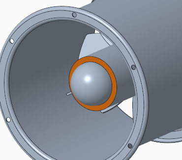
5. To create a sketch:
a. To define the sketch plane, in the graphics window, select the orange ring-shaped surface. The Sketch tab opens.
b. To orient the sketching plane parallel to your computer screen, on the in-graphics toolbar, click
 Sketch View
.
c. To project curves or edges:
a. In the
Sketching group, click
 Project
. The
Type dialog box opens.
b. To select the edges to project, in the graphics window, select one of the outer edges of the orange surface, and then hold down the CTRL key while you select the other outer edge.
c. To select all the geometry inside the loop, in the Type dialog box, select Loop, and click Close. The Type dialog box closes.
d. To draw the sketch:
a. In the
Sketching group, click
 Center and Point
.
b. Select the center of the circle. If needed, zoom in.
c. Drag the circle so it is big enough to surround the ribs.
d. Click
 OK
OK. The
Sketch tab closes.
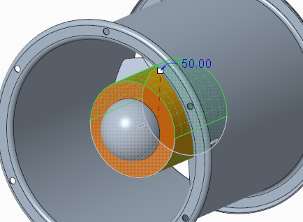
6. To define the depth of the Extrude feature:
a. On the
Extrude tab, click the arrow next to

, and select

, extrude to selected geometry.
b. Click
Saved Orientations on the in-graphics toolbar, and select
VIEW 2.
c. To select the surface to which to extrude the sketch, in the graphics window, select the red surface.
7. Click
. The sketch is extruded to the red surface. The Extrude 1 feature appears in the Model Tree.
The extruded cylinder has the radius that you sketched, outside the fins. Now you will reduce the radius of the cylinder to the original 40 mm.
8. Click
Saved Orientations on the in-graphics toolbar, and select
VIEW 1.
9. Click the
Flexible Modeling tab, and in the
Transform group, click
 Modify Analytic
. The
Modify Analytic Surface tab opens.
10. In the graphics window, select the outer surface of the cylinder that you extruded.
11. In the Radius box, edit the value to 40.
12. Click
. The cylinder now has the same value as before, but the fins are removed.
Remove rounds and chamfers
In this task, first you will remove the round from the center of the ventilator. Next, you will remove chamfers from the base of the ventilator blades. You will do this by recognizing the pattern that the blades follow, remove the chamfers of one blade, and then propagate the pattern to apply the changes to all the blades.
1. Click
Saved Orientations on the in-graphics toolbar, and select
VIEW 3.
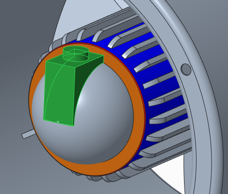
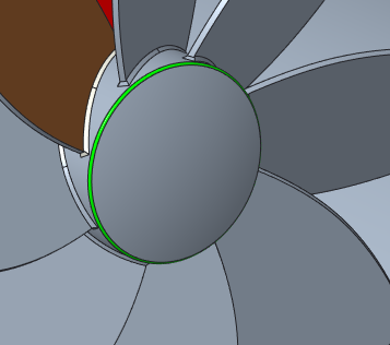
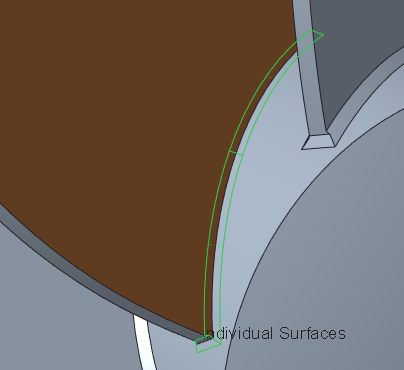
2. To remove the round:
a. Select the green round.
b. In the
Transform group, click
 Edit Round
. The
Edit Round tab opens.
c. On the
Edit Round tab, select the
Remove round check box, and click
. The round is removed. The Edit Round 1 feature is created in the Model Tree.
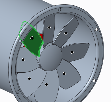
3. To recognize the blade pattern:
a. Select the brown blade surface.
b. To select the entire blade, in the
Shape Surface Selection group, click
 Boss
Boss.
c. In the
Recognition group, click
 Pattern
. The
Pattern Recognition tab opens.
Make sure that all the blades are recognized as pattern members.
d. Click
. The Pattern Recognition 1 feature is created in the Model Tree.
4. To remove the chamfer:
a. Click
Saved Orientations on the in-graphics toolbar, and select
VIEW 4.
b. In the
Transform group, click
Edit Chamfer. The
Edit Chamfer tab opens.
c. On the Edit Chamfer tab, select the Remove chamfer check box.
d. Hold down the CTRL key while you select all the chamfers at the base of one blade.
e. Click
. The chamfers are removed from the base of one blade. The Edit Chamfer 2 feature is create in the Model Tree.
5. To edit the definition of the Edit Chamfer feature to propagate the changes to all pattern members:
a. In the Model Tree, right click the Edit Chamfer 2 feature, and choose
 Edit Definition
 from the popup menu. The
Edit Chamfer tab opens.
b. Click the Options tab.
c. Click the Pattern/Symmetry/Mirror feature collector to activate it.
d. To select the pattern to which to propagate the Edit Chamfer feature, in the Model Tree, select the Pattern Recognition 1 feature.
e. Click
. The chamfers are removed from the base of all the blades in the pattern. The Propagation of Edit Chamfer 2 feature appears in the Model Tree.