To Display a 2D Cross Section View
1. Open a drawing.
2. Double-click an existing view. Alternatively, select a view, right-click and click Properties on the shortcut menu. The Drawing View dialog box opens.
3. Use the View Type category to define the view orientation, such that the view you want to cross-section is oriented properly to the screen.
4. Click the Sections category. The section options are displayed in the dialog box.
5. Click 2D cross-section. The 2D cross-section properties table is enabled. If a 2D cross section does not exist in the drawing, you must create a new one.
◦ Create 2D cross section—If a 2D cross section does not exist in the drawing or if you want to display another cross section, you can create one.
Select Create New from the Name list, located in the 2D cross section table. The XSEC CREATE menu appears on the Menu Manager.
Define the cross section as either Planar or Offset and select the appropriate attributes. Click Done. You are prompted to name the cross section.
Type the desired name and press ENTER. You are prompted to define the cross section reference.
Select an existing reference or create a new one. Only cross sections parallel to the screen are created.
◦ Display existing 2D cross section—If a 2D cross section already exists in the model, you can select it from the Name list in the 2D cross section table. The existing cross sections are listed in alphabetical order. Valid cross section are indicated by

; while

indicates the cross section is not parallel to the screen. A planar cross section must be parallel to the screen. However, you can place an offset cross section if it is not parallel to the screen.
|  Crosshatches for newly created cross sections are displayed based on the value that you have specified for the default_show_2d_section_xhatch Detail option. |
6. After you select a valid cross section name, define how to display the sectioned area. Select one of the visibility styles from the Sectioned Area list:
◦ Full
◦ Half
◦ Local
◦ Full(Unfold)
◦ Full(Aligned)
| You can display Full and Local cross section visibility by defining two cross sections; one with Full visibility and the other with Local visibility. Only one section with Full visibility can exist at any time. |
7. If you are displaying a Half, Local, or Full(Aligned) cross section, you must define placement references. Click the yellow reference collector in the table and select the appropriate reference on the drawing:
◦ Half—Select a datum plane reference. The reference name is listed in the table if the reference is perpendicular to the view.
◦ Local—Select a point reference. Make sure the point reference is outside any other section breakout splines. The geometry name is listed in the table and is displayed on the drawing.
◦ Full(Aligned)—Select an axis reference. All cutting planes of the offset section should contain the reference axis. The axis name is listed in the table and is displayed on the drawing.
8. If you are displaying a Half cross section, define the side of the reference plane that should be sectioned by clicking the drawing on the side of the reference plane.
If you are displaying a Local cross section, sketch a spline encompassing the area you want to display the section in the view.
Make sure the spline does not intersect with other section breakout splines and that the end points meet. The section breakout should not be completely outside the outer border of the view, if there is one. Middle-click when the sketch is complete.
9. You can control the display of model edges by selecting Model edge visibility:
◦ Total—Display model edges behind the section planes as well as section edges.
◦ Area—Displays only section edges.
10. You can flip the direction of the cross section by clicking

. Flipping the cross section does not reorient the model in the view. It only changes which side of cutting plane model material gets removed by the section. You should reorient the view to create a new view orientation for the cross-sectional view.
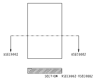
11. If desired, you can document the cross section on a parent view by displaying arrows on that view. Click the highlighted Arrow Display collector in the table and select the view on the drawing. Click Apply to preview the arrows. Arrows are placed, including the name of the cross section at either end. (See illustration below.) You can remove the arrows by right-clicking the collector in the table and clicking remove, or deleting the arrows after they are placed.
12. You can add another 2D cross section to the drawing by clicking and repeating steps 4 through 10.
13. To continue defining other attributes of the drawing view, click Apply and select the appropriate category. If you have completely defined the drawing view, click OK.
| • When the system regenerates a cross section in a drawing, and you add or remove model geometry, it creates new edges in the drawing that you can reference. Because these edges are permanent additions, the model changes when those edges are first created. The model owns the cross section. • You can rename a cross section by right-clicking the cross section name on the 2D cross section properties table and clicking Rename. The system updates the name of the cross-section in the current drawing, in the model that contains the cross section, and in any drawing that was already using the cross section. |