Determining Visible Area of the View
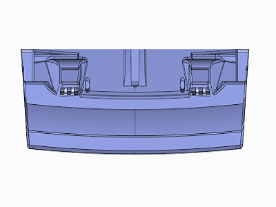
As you detail your model, certain portions of the model may be more relevant than others or may benefit from being displayed from a different view point. You can define the visible area of the view to determine which portion or portions to show or hide.
You can define the visible area of the view from the Drawing View dialog box which can be accessed:
• When you insert a new view.
• Double click an existing view.
• Select and right-click an existing view, and the click Properties on the shortcut menu.
You can define the visible area of the view in the following ways:
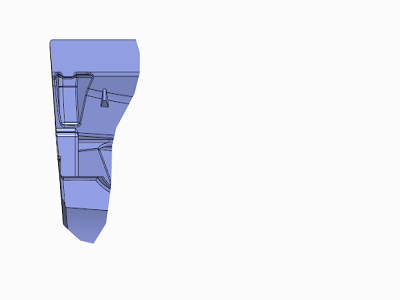
• Half View—Removes a portion of the model from the view on one side of a cutting plane.
• Partial View—Displays a portion of the model in a view within a closed boundary. The system displays the geometry appearing within the boundary, but removes the geometry outside of it.
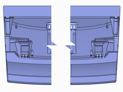
• Broken View—Removes a portion of the model from between two or more selected points, and closes the remaining two portions together within a specified distance. You can break horizontally, vertically, or both, and use various graphic border styles for the breaks.
You can specify a plane parallel to the screen and exclude all graphics behind it. All geometry behind the defined Z-Clipping does not appear, but any geometry that the plane contains entirely does appear. The system clips geometry that intersects the plane. Only the portion in front of the plane appears.


