About Cracks
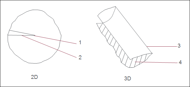
Cracks are idealizations that represent locations in your model where a material has separated, or fractured. Cracks are available only in Native mode. You need an advanced license to define a crack idealization. The following figure shows how cracks are modeled in 2D and 3D models.
1. Crack tip
2. Crack face
3. Crack front
4. Crack face
In a 2D model, the crack is a curve and the tip of the crack is represented by a point called the crack tip.
In a 3D model, the crack is a surface. The edge of the crack inside the model, is represented by a curve called the crack front. You can define a crack idealization by selecting an individual quilt surface or an entire quilt.
After you define a crack, you can define stress intensity factor (SIF) measures. SIF measures determine whether or not the crack will grow under specific loading conditions.
During element creation and during an analysis run, the crack references are treated as hard surfaces in 3D models. They are treated as hard curves in 2D models. Also, the model is split, so that two identical surfaces or curves are created for each of the crack’s reference surfaces or curves.
|  After meshing, if you find the mesh is too coarse near the crack tip you can reduce the value of the configuration option sim_sif_measure_size_factor to a value less than the default value of 0.1. This results in a finer mesh. |
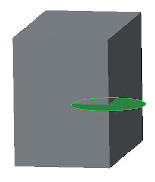
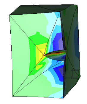
In the following example, Figure 1 shows a crack defined using a circular quilt surface. The quarter circle portion of the quilt surface that cuts into the model is the reference surface for the crack. A tensile force is applied to the model. After you run a static analysis, the crack opens. Figure 2 shows a fringe plot of the displacement results.
|  A 3D crack defined for a volume is ignored if the volume is compressed to a shell. |
|  You cannot create a crack idealization for the following cases: • Intersecting cracks • Cracks that split a volume into two separate volumes • Two or more cracks opening at the same location on the boundary of a volume |


