With Creo Elements/Direct Modeling Express, a Fluent user interface has been introduced for Modeling. The Fluent user interface facilitates faster access to commands by grouping the commands according to their functions.
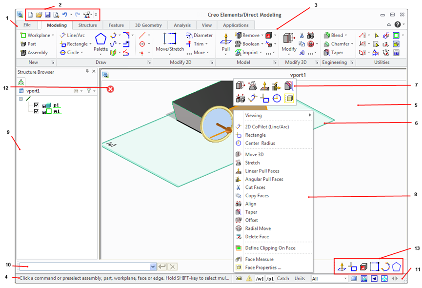
The Creo Elements/Direct Modeling user interface consists of the following elements:
2. Click the CoCreate mouse interaction mode check box in the Dynamic Viewing pane of the Viewport Settings dialog box.
File Tab
The File button in the upper-left corner of the Creo Elements/Direct Modeling window opens the File menu. The File menu contains the following commands:
• New Session: Resets the system to its start-up state.
• Open: Opens a file browser. You can select a file type to load. For more information, see
Load or import files.
• Save: Opens a file browser. You can select a file type to save. For more information, see
Save or export files.
• Print: Prints a model or an assembly. For more information, see
Print a viewport.
• Edit File: Opens a file in a text editor.
• Render to File: Renders the contents of the current viewport to a file. This option is only enabled if the module “Rendering” is active.
• Settings: Changes the Modeling and system settings. For more information, see
Change Modeling settings.
• Toolbox: The Toolbox menu is an empty menu that you can use to place your frequently-used commands.
• Options: Opens the Options dialog box, in which you can customize the Quick Access Toolbar and the Command Mini Toolbar. For more information, see
Customize the interface.
• Exit: Closes Creo Elements/Direct Modeling. Before exiting, you are asked for confirmation.
• Search for Command: Type the name of the command and then select the relevant command from the list to start the command. For example, type Line in the Search for Command box and then select Line/Arc, Spline, or any other relevant command from the list.
• Recent Files: Lists the recently opened files.
Quick Access Toolbar
The Quick Access toolbar is by default at the top of the Creo Elements/Direct Modeling window. It provides quick access to frequently-used commands. You can customize the Quick Access toolbar by adding, removing and reordering commands (buttons and groups) to it.
Ribbon
The ribbon contains commands organized as a set of tabs. On each tab, related commands are grouped. The following figure shows the different elements of a ribbon.
1. Tab
2. Group
3. Button
4. More button
5. Dialog Box Launcher
1. Tab: The default tabs are Modeling tab, Analysis tab, View tab, and Applications tab.
Creo Elements/Direct Modeling Express displays a reduced ribbon. Click the More button to display the complete ribbon with all the available tabs. You can click the Less button to revert to the reduced ribbon.
2. Group: Commands are placed within groups according to their function.
3. Button: Each button on the ribbon represents a command and consists of an icon and, in most cases, a label. Some buttons have an icon and an arrow. The frequently-used buttons are large while other buttons are small in size. The ribbon has the following types of buttons:
◦ or (Large or small button with an icon and a label): Click this button to start an operation. For example, click Move/Stretch to move or stretch a 3D object.
◦ or (Large or small button with an icon and an arrow not separated by a line): An arrow indicates the existence of a list. Click this button to open a list of related commands. When no line separates a button, the icon and arrow perform same action.
◦ or (Large or small button with an icon and an arrow separated by a line): A line, or separation, between the icon and arrow indicates that the icon and arrow perform different actions. Click the icon on this button to start an operation. Click the arrow to open a list of related commands. The icon of the last-selected command in the current session is displayed on the button.
• For some commands, a dialog box opens. See
Dialog Box.
• The label remains unchanged irrespective of the last selection.
• The tooltip shows the name and a description of the command that the icon represents.
• The procedural topics assume that the icon of the default command is displayed on a button though you may see the icon of your last-selected command.
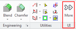
4. More: The rarely-used commands are listed at the end of most groups under the More button to optimize the user interface.
5. Dialog Box Launcher: Opens the settings dialog box related to the commands in the group. For example, click the Dialog box Launcher in the Draw group to open 2D CoPilot Settings dialog box. Draw group includes 2D CoPilot commands.
Prompt Bar
The Prompt Bar is used for general system feedback, messages, or user guidance. The prompt bar is not active by default. If the prompt bar is not open, the prompt text is displayed in the status bar at the lower end of the window. To view the prompt bar:
1. Click View and then, in the Window group, click Toolbars.
2. Click Prompt Bar.
You can position the Prompt Bar anywhere on the screen.
Viewport
The viewport covers the main portion of the user interface. It is the graphics area of the user interface where you design your part.
You can have several viewports to view your part simultaneously from different sides and in different modes. You can resize viewports. The viewport is in between the ribbon and the status bar.
Workplane
A workplane is a transparent, infinite plane. Workplanes allow you to work on any section of your part from any perspective. Use the workplane to draw 2D geometry, machine the part, and create sophisticated shapes.
Command Mini Toolbar
Creo Elements/Direct Modeling opens the Command Mini Toolbar (CMT) when you select any element in the viewport or the structure browser (browser bar) in the preselection mode. The CMT is also displayed when you click in an empty viewport. The CMT is also displayed above the context menu when the context menu is opened. Depending on the current context and the selected object, the elements on the CMT change. The CMT helps you to quickly execute a command from the viewport. The first command on the CMT is the default command. You can customize the CMT. For more information, see
Customize the interface.
Context Menu
The Context Menu opens when you select and right-click any element in the viewport in preselection mode. Depending on the current context and the selected object, the commands on the Context menu change.
Dialog Box
A dialog box opens when you click buttons on the Ribbon, CMT, or the Quick Access Toolbar or some items on the context menu. You can select elements or set properties in the dialog box. Complete or cancel the operation with and , respectively. Click to access help on the current operation.
OK and Cancel
Complete or cancel the operation with the and buttons respectively. These buttons are only available in the viewport (top left corner) if an operation is active. is displayed only if the active operation has a dialog box, which is not displayed in the viewport. You can click to open a dialog box during an operation. For example, if you are pulling a 2D profile to a 3D object, you can click to open the Pull dialog box.
You can press SPACEBAR (or the assigned key) to open the Option Mini Toolbar (OMT) and click on the OMT to open the dialog box during an operation.
Browser Bar (Structure Browser and other Browsers)
The browser bar shows all opened browsers; for instance the structure browser. The structure browser displays all 3D objects and elements (parts, assemblies, workplanes, and so on) and their interrelationships. You can also use the browser to:
• Specify parts and assemblies for Modeling operations; for example, to move a part or an assembly within the structure, and
• Select objects and elements (double-click an object or element in the structure browser).
To open the structure browser, press F12, or:
1. Click View and then, in the Window group, click Toolbars.
2. Click Browser Bar.
User Input Line
The user input line is used to enter commands, general expressions, or text. To view the user input line:
1. Click View and then, in the Window group, click Toolbars.
2. Click User Input Line.
Status Bar
The status bar is at the bottom of the Modeling window and is always available. The status bar has the following commands:
• : Switches the full screen mode on and off (F11).
• : Defines a new viewing window.
• : Displays the last view.
• : Fits the content into the viewport.
• : Switches to previous application.
• : Shows the alert history.
The status bar also shows the current workplane and part and the current settings for Catch and Units. For more information on Catch, see
Catching and catch modes.
Additional modules might add additional entries to the status bar, for instance, module “Parametrics” adds the current relation set.
If the prompt bar is not open the prompt text is displayed in the left side of the status bar.
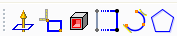
Recent Commands Toolbar
The Recent Commands Toolbar displays the recently-used commands at the bottom-right corner of the viewport. You can use this toolbar to quickly select a recently-used command. The following image shows an example of the Recent Commands Toolbar; you can click to start the Polygon command and draw polygons in the viewport.
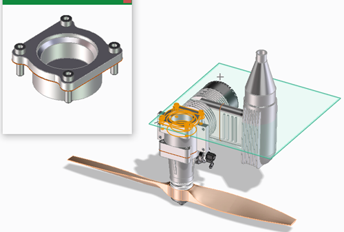
A preview window opens when you middle-click a part or an assembly in the Structure Browser. The part or assembly is highlighted in the viewport as shown in the following image. The preview window is updated when you middle-click a different part or assembly. You must explicitly close the preview window.
 Line/Arc,
  Spline, or any other relevant command from the list.
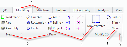
 or
or  (Large or small button with an icon and a label): Click this button to start an operation. For example, click Move/Stretch to move or stretch a 3D object.
 or
or  (Large or small button with an icon and an arrow not separated by a line): An arrow indicates the existence of a list. Click this button to open a list of related commands. When no line separates a button, the icon and arrow perform same action.
 or
or  (Large or small button with an icon and an arrow separated by a line): A line, or separation, between the icon and arrow indicates that the icon and arrow perform different actions. Click the icon on this button to start an operation. Click the arrow to open a list of related commands. The icon of the last-selected command in the current session is displayed on the button.
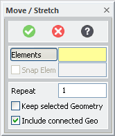
 and
and  , respectively. Click
  to access help on the current operation.
 is displayed only if the active operation has a dialog box, which is not displayed in the viewport. You can click
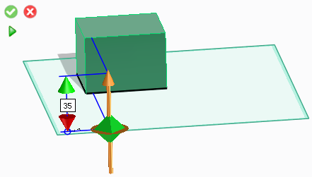
 : Switches the full screen mode on and off (F11).
 : Defines a new viewing window.
 : Displays the last view.
 : Fits the content into the viewport.
 : Switches to previous application.
 : Shows the alert history.
 to start the Polygon command and draw polygons in the viewport.