When you bring new data into Creo Elements/Direct Modeling, you can load
• Models
• Assemblies
• Drawings
• Entire environments, which might include 3D designs, light settings, background colors, and more.
Models and assemblies will appear in your current viewport, beside any other data already in the viewport. However, when you load a session file, all existing parts, assemblies, workplanes, and workplane sets will be lost.
• When you load a package file (.pkg), a bundle file (.bdl), or a session (.ses) file from a directory (file system) or from Creo Elements/Direct Model Manager, a Progress Bar, which shows the progress of the file that is being loaded, appears on the Status Bar.
• When you load a 3D Data file (.sd*), the Progress Bar does not appear on the Status Bar.
• When you load a model that contains decal information, you can see decal information only when you activate the Rendering module. For more information, see Using decals.
Drawings (MI files) are loaded as 2D geometry in a workplane. Use Import 2D to drawing (*.mi;*.bi;*.dxf;*.dwg;*.igs;*.iges) and select a drawing file (MI, DXF, DWG) to start Creo Elements/Direct Annotation and load the drawing. Bundle files can be loaded in Creo Elements/Direct Modeling; if Creo Elements/Direct Annotation is not running, it will start and load the 2D drawing part of the bundle.
Use Import 2D to workplane (*.mi;*.lyt;*.dwg;*.dxf) and select a drawing file (MI, DXF, DWG) to directly load drawings (DWG and DXF files) in the active workplane in Creo Elements/Direct Modeling, without starting Creo Elements/Direct Annotation. The 2D geometry, with color and line types, is loaded in the active workplane.
When you load some parts from the database, the parts are loaded with their modified flags set. This is because the information at the instance level, which is stored with the assembly, is no longer loaded. Instead, a default instance is created with the default values. So if you change the part color while the part is in an assembly, when you load just the part, the part appears modified and changes back to the default grey color.
Filename conversion
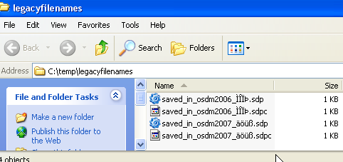
In CoCreate Modeling 2006 and earlier, file names were written in legacy encoding, that is, Roman8 or SJIS. This is why German umlauts in Creo Elements/Direct Modeling file names looked funny when viewing them in Windows Explorer. To compensate for this effect, the Creo Elements/Direct Modeling file browser used to automatically convert the file names it displays so that umlauts and accented characters looked correct for files stored by Creo Elements/Direct Modeling.
Newer versions of Creo Elements/Direct Modeling write file names in UTF-16 encoding, i.e., in an encoding that the operating system expects and fully supports. Hence, special conversions are no longer required in the file browser.
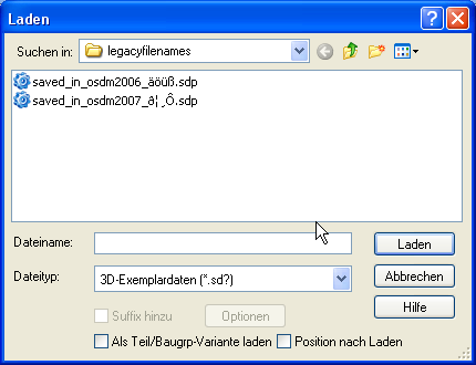
Consequently, names of files written in earlier versions of Creo Elements/Direct Modeling are now listed in the file browser in the same way as in a standard Windows Explorer window - which means that the umlauts look incorrect. Because new files are always written in the encoding expected by the operating system, this problem will decrease over time. However, if you have numerous legacy files affected by this problem, there is an option you can use to re-enable the old automatic filename conversion.
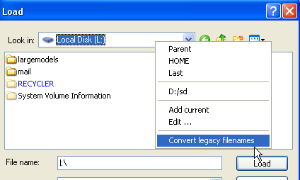
It's located in the context menu for the file browser's Look In control and called Convert legacy filenames:
Check this option to enable automatic conversion. When the file browser is closed, default behavior is reinstated (i.e., no conversion).
In legacy filename mode, the file browser performs filename conversions in the same fashion as CoCreate Modeling 2006 and earlier. As a result, legacy file names display with legible umlauts and accented characters, but new file names won't:
Language settings
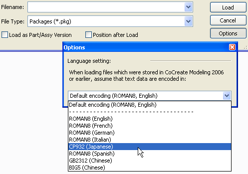
When loading old (native) Creo Elements/Direct Modeling files, or when saving Creo Elements/Direct Modeling files in backwards-compatible mode, you can control how your model's string data are converted. This is important in the following example scenarios:
• A German user starts the German version of Creo Elements/Direct Modeling
• The German user wishes to load a model stored in CoCreate Modeling 2006 by a Japanese coworker.
By default, Creo Elements/Direct Modeling assumes that legacy data contain characters in the same language in which Creo Elements/Direct Modeling started. In the particular case described above, this strategy would fail.
For a simple workaround, the German user could restart Creo Elements/Direct Modeling in Japanese and load the file. This could be inconvenient, however, especially if the Japanese language version of Creo Elements/Direct Modeling isn't installed.
For this reason, you can optionally control the conversion from the user interface. In the above example, the German user would do the following:
1. Click File > Open.
2. Select a native file type (*.sd, .pkg, .bdl), depending on the type of file provided by the Japanese co-worker.
3. Click Options.
4. In the Options dialog box you can specify the encoding used for legacy files. The German user chooses CP932 (Japanese), then loads the file.
This special language setting is only effective during a single filing operation. When the filebrowser closes, Creo Elements/Direct Modeling reinstates the default behavior. When saving model data, the special Language Settings options only become accessible when saving in backward-compatible mode.
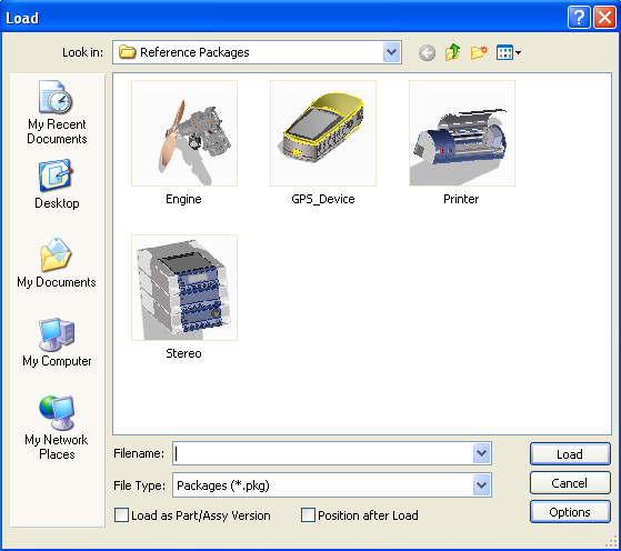
To load or import a file,
1. Click File > Open. The Load dialog box opens.
2. Select a File Type.
You can see realistic thumbnail representations of package and bundle files in the Thumbnails view. However, realistic thumbnails are available only for files that were created or saved in Creo Elements/Direct 19.0 or later versions. Similarly, you can also see realistic thumbnails in Windows Explorer.
3. Click Load as Part/Assy Version to load a model incrementally that you wish to save as a version.
4. Select the Position after Load check box to start the positioning of parts automatically.
If the Position after Load check box is selected and an assembly already exists in the viewport, the loaded model is positioned at the center of and in front of the assembly. An auxiliary view window also opens by default, which shows the position of the model. You can select the model and use the 3D CoPilot to change its position. Toggle the display of the auxiliary view window using the Position dialog box.
5. If you have selected the File Type as 3D Instance Data (*.sd?) and the Position after Load check box, the Place At Instance Position check box is visible. Select the Place At Instance Position check box to load and position 3D instance data at the position specified in the instance file instead of at the center.
6. If necessary, click Options and specify additional parameters for the load operation. This button is active only for certain file types. For all proprietary Creo Elements/Direct Modeling formats you can specify the default encoding of pre-15 non-Unicode files. Click the help button for more information about other load options.
7. Select the file to load or type its name in the Filename field.
8. Click Load.
Right-click in the Look in field for a list of user-defined project folders. Please read
Configure project folders for more information.