• If you select a 2D edge, Creo Elements/Direct Modeling automatically sets the direction perpendicular to the workplane of the 2D edge.
• If you select a 3D edge, you must select the direction as explained in the following steps.
4. Under Method, click Linear.
By default, Linear is selected.
5. Click Direction and use the Direction 3D CoPilot to specify a pull direction in one of the following ways:
◦ Using another edge:
1. Move the cursor (hover) over another edge.
2. Click to apply the direction. For more information, see
Direction 3D CoPilot.
◦ Using a workplane:
1. Move the cursor (hover) over a workplane and click to fix the position of the U, V, and W direction arrows. For more information, see
Direction 3D CoPilot.
2. Click the U, V, or W arrow to apply the direction.
6. Type a value in the Distance box or drag (or click and move) the Vector 3D CoPilot dragger to specify the pull distance.
7. To create a tapered face, click Draft Angle and type a value for the angle. The selected edges remain fixed.
8. Click to complete the operation.
To angularly pull edges,
1. You can open the Pull Edges dialog box in any of the following ways:
◦ Using the Modeling tab:
1. Click Modeling and then, in the Model group, click the arrow next to Pull.
• If you select a 2D edge, Creo Elements/Direct Modeling automatically sets the direction perpendicular to the workplane of the 2D edge.
• If you select a 3D edge, you must select the direction as explained in the following steps.
4. Under Method, click Angular.
By default, Angular is selected.
5. Click Axis and use the Axis 3D CoPilot to specify a rotation axis in one of the following ways:
◦ Using another edge:
1. Move the cursor (hover) over another edge.
2. Click to apply the direction. For more information, see
Axis 3D CoPilot.
◦ Using a workplane:
1. Move the cursor (hover) over a workplane and click to fix the position of the U, V, and W direction arrows.
2. Click the U, V, or W arrow to apply the direction. For more information, see
Axis 3D CoPilot.
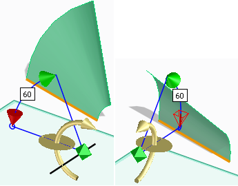
6. Type a value in the Angle box or drag (or click and move the cursor) the Axis 3D CoPilot dragger to specify the pull angle as shown in the following images.
7. Click to complete the operation.
If the edges are connected, one face part is created. If the edges intersect, two face parts are created.
 Pull.
Pull. Pull Edges Linear. The Pull Edges dialog box opens.
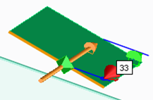
 to complete the operation.
 Pull Edges Angular. The Pull Edges dialog box opens.