Context menus contain frequently-used commands and operations. Not only are there several ways to display these menus, but the menu contents depends on your current activity:
• Right-click in the viewport to display available Viewport options such as Redraw, Window, and Fit.
• Right-click a toolbar to show/hide toolbars. Check the ones you want to display.
• Press SHIFT and right-click in the viewport to display available Catch, Select and other related options.
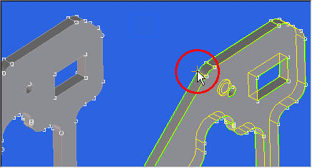
• Right-click in the viewport while in preselect mode (element, face highlighted) to display available machining or similar commands such as Blend Create. For more information on preselection, see
Intelligent preselection with context menus.
• Right-click a box (data entry field) to display various data input possibilities, shortcuts to the select and measure functionality. Press SHIFT and right-click to display a list of Last Values for you to select from.
Intelligent preselection with context menus
Creo Elements/Direct Modeling lets you select elements (for example, edges, faces, or workplanes) and display the various operations that can be performed on that element with a single right-click. For example, move the pointer over an edge until the edge is highlighted and then right-click. Creo Elements/Direct Modeling displays a context menu. Select Blend Create and specify the necessary inputs in the usual manner. This technique is sometimes referred to as fly-by preselection and can be customized.
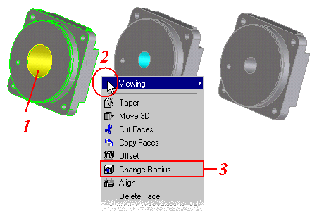
The following figure gives an example of how to use preselection to modify the diameter of a bored hole.
1. Position the pointer over the face of the bored hole until it is highlighted in yellow.
2. Right-click. By default, the contents of this menu includes the command Change Radius.
3. Click Change Radius to display the Modify 3D / Change Radius dialog boxes.
Intelligent preselection can speed-up the design process by reducing the number of steps. The alternative method in the previous example is to click the command sequence: Click Modeling and then, in the Modify 3D group, click Radius and then select the cylindrical face.
The contents of the preselection context menus are customizable. For example, you can add the Lift command to your favorite preselection context menu.
Preselection of parts
With fly-by highlighting switched on during preselection, it is easy to select whole parts. Simply position the mouse cursor next to a vertex point on the part and see the complete part being highlighted. Now click either the left or right mouse button to preselect the highlighted part.
Although the following example shows Vertices switched on, this is not necessary to achieve preselection of parts.
This setting switches this behavior off. That is, a right-click on a highlighted element/object, does not automatically select the element/object. However, this behavior can be forced to be on even if fly-by is off. Usually the right-click behavior is switched off automatically if fly-by highlighting is switched off. To switch automatic preselection on with fly-by switched off, set the following:
(agent:set-auto-preselect-on-fly-by-right-click t :force t)
The application's default is:
(agent:set-auto-preselect-on-fly-by-right-click t :force nil)
Properties of preselected objects
Property dialogs are available if any of the following objects is in preselect mode:
In order to access a property dialog, an object must first be preselected. Clicking the right mouse button pops up a context menu where (by default) the last menu entry offers access to the corresponding property dialog.
A Property dialog box shows the object's properties at a glance. Additionally, the dialog also allows you to change any of the displayed values. Changing one of the properties results in an immediate update of the selected object.
From a property dialog, further dialogs can also be launched:
• The Copy to button opens a dialog offering the capability to copy all or some properties from the currently preselected object to one or several other objects of the same type.
Depending on whether a check box for a specified property is set, the corresponding value is transferred to the selected target objects.
• The Copy from button opens a dialog offering the capability to copy properties to the preselected object from a specified object. In this case the source object and destination object must be the same type.
All properties of the selected source object are displayed under Source Properties in the dialog box. The check boxes in the upper half of the dialog box allow you to specify individual properties to copy.
• For some object types, access is available to start measure commands or to display a report summary of geometrical properties.
• For some object types, default properties are defined. In order to apply these default properties to the preselected object, click the Default button. Usually the default properties are set in the corresponding default settings dialog for the underlying object type.
• Grid properties: In order to minimize a complex property dialog for a preselected workplane, the grid properties of a workplane are accessed through a separate grid property pane.
• Part Properties: All part properties are displayed as they are realized in the viewport. Changing a part's property means changing a property of the instance.
 Radius and then select the cylindrical face.