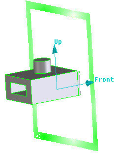
Create drawings from models (Creo Elements/Direct Annotation) > Turn 3D models into 2D drawings > Create views > Create an isometric view
  
Create an isometric view
Creo Elements/Direct Annotation provides eight isometric view options in the Add Views dialog box. The direction of the isometric view depends on the Front and Up viewing directions defined for the drawing or the view owner, and on the Set the default drawing/view settings.
The figure shows examples of the isometric views.
In the figure, the isometric views on the right are generated based on the Creo Elements/Direct Modeling model on the left. The isometric view options are the following:
View
Isometric Option
1
LftTopFrnt—for a left/top/front view
2
RgtTopFrnt—for a right/top/front view
3
LftBotFrnt—for a left/bottom/front view
4
RgtBotFrnt—for a right/bottom/front view
5
LftTopBck—for a left/top/back view
6
RgtTopBck—for a right/top/back view
7
LftBotBck—for a left/bottom/back view
8
RgtBotBck—for a right/bottom/back view
To create an isometric view,
1. Click Annotation and then, in the Setup group, click New Std View. The Add Views dialog box opens.
2. The current drawing Owner, Front Dir, and Up Dir are the default values. The default value for Scale is that of the current sheet. Enter new values as required.
3. If you have configurations in your 3D assembly with the same owner as that of your view,
You may select a configuration from the Configuration drop-down menu on which to base your new view.
If your configuration includes a drawlist, click Drawlist and choose No, Once, or Always to select whether to apply the drawlist to the view.
4. Select one or more Isometric Views.
5. Select a Profile.
6. Move the view placeholders for the selected views and click to place them on the sheet. You can click Reposition Views in the Add Views pane to move the views to a different location.
7. Click to complete the operation.
The view can now be updated with the Update command. You can continue adding views and then update them in one operation.