FMEA Construction
FMEA construction begins by selecting the appropriate worksheet from the many variations that are available, keeping in mind the analysis objective, design data availability and item indenture level. The heading of a FMEA worksheet can contain fields for subject line, team leader, team members and dates for the project deadline as well as for update and maintenance revisions. In MIL-STD-1629, the worksheet for Task 101 has the header information in Table 6-3. The Task 101 worksheet is shown in Figure 6-1.
|
Header Field
|
Description
|
|---|---|
|
System
|
Item for which the FMEA worksheet is being completed.
|
|
Indenture Level
|
Level at which the item resides within the system hierarchy.
|
|
Reference Drawing
|
Drawings used to determine and document the failure modes and effects for the item.
|
|
Mission
|
Tasks to be performed and the mode of operation for performing these specific functions.
|
|
Date
|
Date on which the FMEA worksheet is developed, or dates on which worksheet was last updated.
|
|
Sheet ___ Of ___
|
Number of FMEA worksheet pages for the item.
|
|
Compiled By
|
Team member(s) responsible for developing the FMEA worksheet.
|
|
Approved By
|
Person authorised to approve the FMEA worksheet.
|
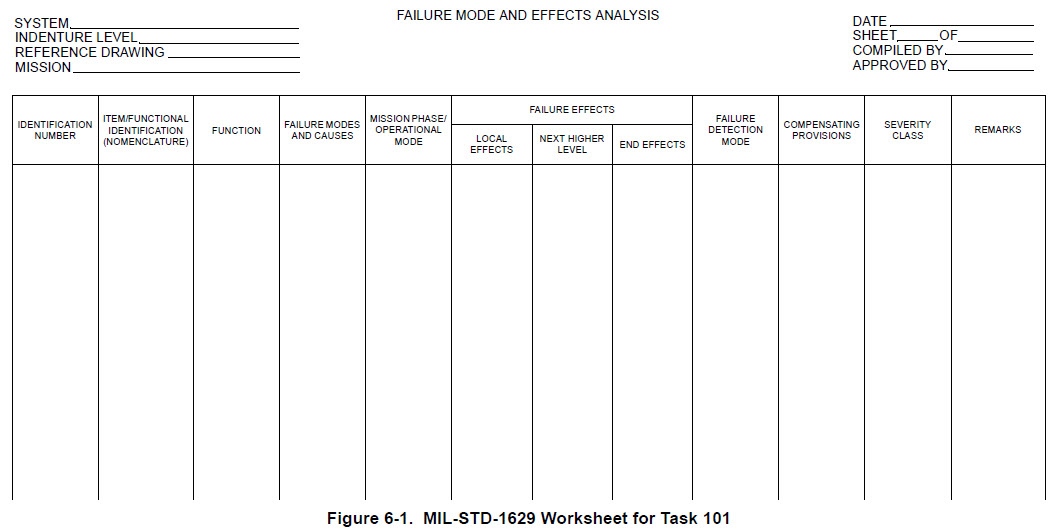
General descriptions of the columns in the Task 101 worksheet appear in Table 6-4. Although worksheets for analysing failure modes and their effects do vary, they all request the same information for assessing how system operation is affected.
Field | Description |
|---|---|
Identification Number | Serial number or other unique reference designator that has been assigned for traceability purposes. This identification number is consistent with those used on the functional and reliability block diagrams for this item. These block diagrams are referenced in the Reference Drawing field in the worksheet header. |
Item/Functional Identification (Nomenclature) | Name of the item or system function for which failure modes and effects are to be identified. Schematic diagram symbols or drawing numbers are used to identify the item or function properly. |
Function | Concise statement of all the functions that the item is supposed to perform to accomplish its intended purpose to the satisfaction of the customer. Included are both inherent functions of the item and its relationships to interfacing items. Within a functional FMEA, the function is a description of the task, duty, action or operation performed by a group of elements at the functional block level. |
Failure Modes and Causes | Potential failure modes that have been identified for each indenture level to be analysed based on stated requirements and failure definitions. To uncover potential failure modes, examine the item outputs and functional outputs in the applicable block diagrams and schematics, and review historical field and test data; if a team approach is being used, hold a brainstorming session to see if additional failure modes and causes can be identified. Causes for the failure mode, which are either the reasons for the failure or those which initiate the processes that lead to the failure (design defects, quality defects, part misapplication, physical process, chemical process, etc.). Multiple causes can be assigned to each failure mode. |
Mission Phase/ Operational Mode | Mission phase and operation mode in which the failure occurs. If the sub-phase, event or time can be defined from the system definition and mission profiles, include timing information for the failure occurrence. |
Failure Effects | Consequences of the failure mode on the operation, function or status of an item as they are likely to be experienced by the customer. (Often times, historical field data from a similar design can be used to compile a list of effects.) Because the failure mode under consideration may affect the system at several levels, failure effects are related to the functions at the next higher level of the design, continuing progressively to the top or system-level functions. • Local Effects–Consequences that the failure mode has on the local operation, function or status of the specific item that is being analysed. Describe the fault condition in sufficient detail so that it can be used to determine the next higher level effects and end effects. • Next Higher Level–Consequences that a failure mode has on the operation, function or status of the items in the indenture level above the one under consideration. • End Effects–Consequences that a failure mode has on the operation, function or status of the highest indenture level. |
Failure Detection Method | Techniques for detecting the failure mode or corresponding causes, including design reviews, process control plans, test plans, reliability plans, etc.. |
Compensating Provisions | Design provisions or operator actions that can be taken to circumvent or mitigate the effect of a failure on a system but do not prevent its occurrence. Design provisions include redundant items that allow safe operation to continue in the event of failure, safety or relief devices such as monitors or alarms that permit effective operation or limits damage, and adding alternative modes of operation such as backup or standby items or systems. Operator provisions include providing operating procedures and installing built-in test (BIT), monitors, fault detectors and gauges. |
Severity Classifications | Provides a qualitative measure of how serious the consequences of the failure mode are on the system, mission or application. Severity classifications for Task 101 are Catastrophic, Critical, Marginal and Minor. Rating scales should be tailored to fit the specific industry or organisation based on customer perception. The corporate FMEA standard should describe all ranking scales that can be used, and the FMEA plan should indicate which of these ranking scales are to be used for the given system. When determining which failure modes to address, prioritization is dependent upon severity (FMEA) or severity and criticality (FMECA). For detailed information on determining the most critical failures modes, refer to Criticality Analysis. |
Remarks | Comments pertaining to and clarifying other columns in the current line of the worksheet, including notes about unusual conditions, failure effects of redundant items and recognition of particular critical design features. Recommendations for design improvements to be pursued based on the quality or reliability payback for the customer, organisation and society. Keep in mind that the goal is to eliminate the root causes of a failure mode, which include: incorrect material specification, overstressed components, insufficient lubrication, inadequate maintenance instructions, poor protection from environment, incorrect algorithms, software design errors, etc.. Only notes regarding recommended corrective actions and their importance need to appear here. Recommended corrective actions are to be fully described in the summary of the finalised FMEA report. When the recommended corrective actions require significant resources or high risk, they must be investigated further and cost/benefit studies must be performed. Comparing estimated warranty costs to development costs of the proposed change to the current design can determine the appropriate corrective action. When design changes are not possible, compensating provisions must be identified. |
Most designs have more than one failure mode. To avoid debating whether an event is a mode, effect or cause, express the failure mode as the function in a negative sense. For example, if the function is that the item is to heat, the failure mode is that it does not heat.
Although the primary goal of FMEAs is to prevent potential failure modes, reducing the effects from failures (based on severity and possibly detection) must be carefully considered so that unnecessary costs are not incurred for failure modes having little negative impact on the customer. As severity and occurrence decrease, it is generally less expensive to provide detection than to investigate alternatives to improve the design.