Example of Application
An example of the use of the failure rate model for a hybrid device and the data tables follow.
Example Hybrid Microcircuit Device
Task
A hybrid microcircuit device is being used in a ship protected environment at a package temperature of 65°C. The device has 28 gold/aluminium connections; 6 solder connections, 1 die linear with 16 transistors; 1 die linear with 24 transistors; 2 Si PNP transistors, power < 5w at 50% stress ratio; 4 Si diodes, power > 20w at 50% stress ratio; 4 capacitors, ceramic chip, 50% stress ratio; and 14 network, thick film resistors with 5-10% tolerance. The package is a hermetic flat pack with a seal length of 1.2 inches by 0.8 inches, and the substrate dimensions are 0.8 inches by 0.6 inches. The device is to be procured under BS 9000 screening level S2. Predict its failure rate.
Solution
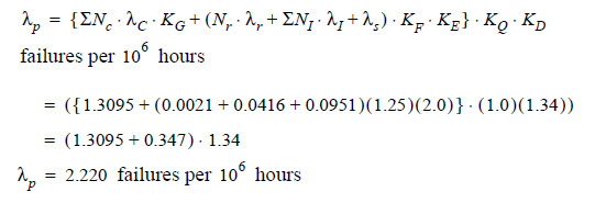
1. The hybrid microcircuit device model applies. That is, from equation (3.5)

failures per 106 hours.
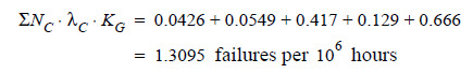
2. Calculate ΣNcλCKG, which is the sum of the adjusted failure rates of the two linear die, the two transistors, the four diodes and the four capacitors:
Linear Die 1 and 2
▪ Refer to Data Tables, and determine the model appropriate to the linear die, i.e., from Table A-40:
▪ From the Data Tables tables, determine the appropriate base failure rates and factors for each die, as follows:
Table | Factor | Die 1 | Die 2 |
KG | 1.0 (S2 Screening level) | 1.0 (S2 Screening level) | |
C1 | 0.0046 (16 Transistors) | 0.0063 (24 Transistors) | |
C2 | 0.012 (16 Transistors) | 0.015 (24 Transistors) | |
KE | 4.0 (Ship protected) | 4.0 (Ship protected) | |
KT2 | 5.0 (Linear device Ttj=75°C) | 5.0 (Linear device Ttj=75°C) |

▪ From Table A-48:
KG=0.6 for each device (both linear)
▪ There is one of each die so, in each case, NC=1. Therefore, from above, NCλCKG for each die is:
▪ Die 1 = (1.0)(0.07)(0.6) = 0.0426 failures per 106 hours
▪ Die 2 = (1.0)(0.0915)(0.6) = 0.0549 failures per 106 hours
Discrete Components
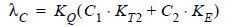
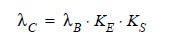
▪ Determine the model appropriate to discrete components, that is:
▪ From Data Tables tables, determine the appropriate base failure rates and factors for each type of component, as follows:
Value | Transistor | Diodes | Capacitors |
|---|---|---|---|
λB | 0.07 | 0.20 | 0.10 |
KE | 5.9 (Ship protected) | 1.2 (Ship protected) | 1.2 (Ship protected) |
KS | 1.26 (6°C ) (0.5 stress ratio) | 0.67 (65°C) (0.5 stress ratio) | 1.73 (65°C) (0.5 Stress ratio) |
λC=λBKEKS | 0.521 | 0.161 | 0.208 |
Transistors | Diodes | Cpacitors | |
|---|---|---|---|
KG= | 0.40 | 0.20 | 0.80 |
▪ From above, NCλCKG or each discrete component type is, as follows:
Component Type | NC | λC | KG | NCλCKG |
|---|---|---|---|---|
Transistors | 2 | 0.521 | 0.40 | 0.417 |
Diodes | 4 | 0.161 | 0.2 | 0.129 |
Capacitors | 4 | 0.208 | 0.80 | 0.666 |
c. From Steps a and b
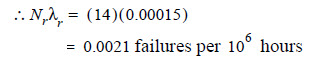
3. Calculate Nrλr, which is the failure rate of the network resistors. For the number of network resistors, Nr=14. From Table A-49 ( package temperature), λr failures per 106 hours.
Connection Type | N1 | λ1 | N1λ1 |
Gold/Aluminium | 28 | 0.0013 | 0.0364 |
Solder | 6 | 0.000871 | 0.0052 |

6. Determine the appropriate values for the factors KF, KE, KQ and KD.

7. Calculate the predicted failure rate, λp, by substituting the results from Steps 2 through 6 in the failure rate model in Step 1.