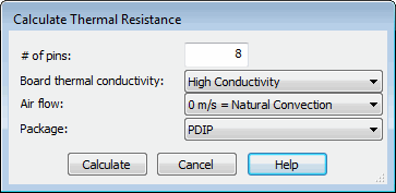
Thermal Resistance for a FIDES Integrated Circuit
When a FIDES model for parts stress analysis is selected for the top-most assembly, a button for calculating thermal resistance appears in the Prediction Data pane for an integrated circuit. When you click Thermal Resistance, the Calculate Thermal Resistance window for this FIDES part opens. The parameters required by a FIDES model for an integrated circuit differ from those required by other models

The following table describes the parameters that appear in this window for a FIDES integrated circuit.
Parameter | Data Type | Description |
|---|---|---|
# of pins | Numeric - Integer | The number of active pins in the package. The default is the value entered for Pins in the Prediction Data pane. |
Board thermal conductivity | Predefined List | Indicates whether the conductivity of the board is high or low. |
Air flow | Predefined List | Indicates whether the air flow is 0 m/s, which is natural convection, or 2 m/s. |
Package | Predefined List | The type of package for the integrated circuit. Dozens of choices are available. |
After you specify values for these parameters and click Calculate, the thermal resistance of the FIDES integrated circuit is computed. Thermal Resistance, which appears on the lower right side in the Prediction Data pane, shows the result.