Thermal Resistance Calculations for Integrated Circuits
When the IEC TR 62380 or RDF 2000 model is selected, for an integrated circuit, you must specify a thermal resistance. Thus, the reliability prediction standards for these models provide equations for calculating thermal resistance for integrated circuits in case these values are not specified by the manufacturers. To compute the thermal resistance for an integrated circuit, you enter values in the Calculate Thermal Resistance window, regardless of the model that is selected. For more information, see Calculate Thermal Resistance Window.
The general equation for computing the thermal resistance for an integrated circuit is:
Junction-ambient thermal resistance = junction-case thermal resistance + case-ambient thermal resistance
The specific equation that is used to calculate thermal resistance depends on the package type of the integrated circuit. The equation for a particular package type includes S and K values, where S is the number of pins in the package and K is the cooling airflow factor according to the velocity of air, V(m/s), which is given by the following equation:

The following table provides default values for the thermal resistance of integrated circuits as a function of S and K. Practical values for K are given the subsequent table.
Package Type | Junction-Case Thermal Resistance  | Junction-Ambient Thermal Resistance  |
|---|---|---|
DIL ceramic | 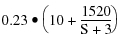 | 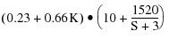 |
DIL plastic | 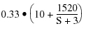 | 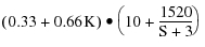 |
PLCC plastic | 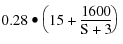 |  |
SOJ and SOL plastic | 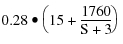 | 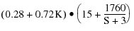 |
TSOP plastic | 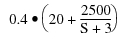 |  |
PGA ceramic | 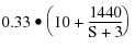 |  |
QFP plastic | 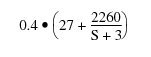 |  |
BGA plastic | 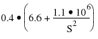 | 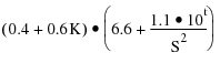 |
The following table provides typical values for air flow speed, V, and the air flow factor, K.
Method | V(m/s) | K |
|---|---|---|
Natural convection | 0.15 | 1.4 |
Slightly assisted cooling | 0.5 | 1.2 |
Fan-assisted cooling | 1.0 | 1.0 |
Forced cooling | 4.0 | 0.7 |