Reliability Block Diagrams
A Reliability Block Diagram (RBD) is a method of representing, in a single and visual way, the reliability relationships between the system and the items in the system. It can also be regarded as a model of a system failure/success definition. It does not necessarily relate to the physical connection of components or sub-units.
A system may require more than one RBD if it has to perform several functions or if it experiences several different operating states. In essence, the RBD must show the flow of inputs and outputs required for a particular function of the system being considered. It should be noted that the events modelled by RBDs must be totally independent of each other.
|
|
Other methods of establishing the reliability relationships between items, such as Fault Trees and Truth Tables, are not considered in this chapter. However, additional information on Fault Trees is presented in Fault Tree Analysis. (For additional information, see Bibliography.)
|
An example of an RBD is shown in Figure 2-3. For additional information, see Preparation of Reliability Block Diagrams.
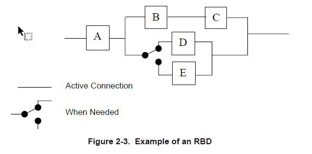
In Figure 2-3, it is assumed that both the system and its constituent items are in one of two states: either functioning correctly or failed. Hence each item may be looked on as a switch that is closed when the item is functioning and open when it has failed. The system will only function when a path exists between the input and output nodes. Thus, the system in Figure 2-3will fail to function when at least:
• Item A has failed OR
• Item B or C has failed AND
◦ Item D has failed AND
◦ Item E has failed.
This can be written in Boolean notation in the form:  |
An RBD can always be constructed as connected groups of three types:
• Items in series (e.g., B and C in Figure 2-3).
• Items in parallel (or active) redundancy (e.g., B and D or C and D in Figure 2-3).
• Items in standby (or passive) redundancy (e.g., D and E in Figure 2-3).
From Figure 2-3, it can be seen that items A, B and C are sufficient to perform the desired system function. However, item D, which is operating simultaneously, is included in the system as an alternative means of helping to perform the system function. This is termed parallel (or active redundancy). Item E also provides an alternative, but remains inoperative until needed. This is termed standby (or passive redundancy)/ |