Examples of Reliability Modelling
This simplified example is intended to illustrate the reliability modelling process at system/sub-system level. The subject of the example is a hypothetical Guided Weapon System (GWS) that, in general terms, is required to be a land-based, mobile system to search for, detect, track, intercept and destroy airborne targets.
Step 1: Define the Operational Requirements and Constraints
Assume that, from the study of the customer documents, the requirements and constraints area as follows:
◦ Operational. With any 24-hour battlefield day, to be capable of:
▪ 14 hours at alert state with one target engagement of 2 minutes.
▪ 10 hours at non-alert state, including one redeployment involving 2.5 hour cross-country movement.
◦ Maintenance:
▪ Missile to be no-test and capable of 5 years storage before firing.
▪ Launcher not repairable during alert state.
▪ Radar to be repairable on site, with mean time to repair not exceeding 20 minutes.
◦ Reliability. A probability of at least 97.5% that successful intercepting of a target is not prevented by a system hardware failure (including the missile and its flight) during a 24-hour battlefield day.
Step 2: Define the system functions, configuration and failure criteria.
◦ The function of the system is to intercept and destroy enemy targets. This overall function is comprised of three main elements:
▪ Target Search and Detection (Fl).
▪ Target Tracking and Pre-launch Guidance Commands (F2).
▪ Launch Commands and Target Interception (F3).
◦ The proposed design consists of a Search Radar (SR), a Control Unit (CU), a Tracker Radar (TR) an alternative Manual Sight (MS) and two Launchers (Ll and L2), with each Launcher containing two Missiles (Ml, M2 and M3, M4). The Search Radar operates continuously during an alert state and passes search data to the Control Unit. When a target is detected, the Tracker Radar is brought into operation and provides pre-launch guidance information via the Control Unit to the two Launchers and their Missiles. The Manual Sight provides an alternative method to tracking targets. A functional block diagram of the system is shown in Figure 4-6.

◦ The sub-systems associated with the system functions are as follows:
Function | Performed By |
|---|---|
F1 | SR and CU |
F2 | CU, TR, MS, L1/2 |
F3 | CU, L1/2, M1/2/3/4 |
A system failure is defined as any failure in the system hardware that prevents the successful interception of a target. Thus, failure to perform any one of the three system functions (Fl, F2 and F3) constitutes a system failure.
Step 3: Define Operational Duty Cycles.
From consideration of the requirements detailed in Step 1, the operational duty cycles for the system and sub-systems are as shown in Figure 4-7.

T=Setting up tests, involving 15 minutes operating and 1 switching cycle. |
Standby means that the equipment is warmed up and ready for immediate use but is not fully operational. |
Environments. The Ground Mobile environmental category applies throughout all cycles, except for Missile storage, boost and flight. |
Repairable on site during the Alert state; Mean Time To Repair (MTTR) not exceeding 20 minutes. |
The cycles are related to a 24-hour battlefield day because this is the time interval specified for the reliability requirement. However, the duty cycle for the missiles must also include the requirement for up to 5 years storage prior to their operational use. |
Step 4: Construct Reliability Block Diagrams (RBDs).
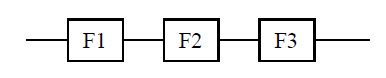
The minimum requirements for the system to operate successfully are that all three functions, Fl, F2 and F3 must be performed. Thus, successful operation of the system can be represented by:
◦ The sub-systems required to perform functions F1, F2 and F3 successfully are as follows:
Function | Performed By | Figure |
F1 | SR and CU | |
F2 | TR and CU and L1 or L2 or MS and CU and L1 or L2 | |
F3 | CU and L1 and M1 or M2 or CU and L2 and M3 orM4 |
The RBDs for each of these functions are shown in Figure 4-8. Note that ‘and’ equates to a series configuration and ‘or’ to a parallel configuration.
◦ Because Fl, F2 and F3 must all be performed successfully for the system to perform its functions successfully, the individual RBDs can be combined in series to give the RBD for the system as shown in Figure 4-8d.
Step 5: Construct the Reliability Model for the System/Sub-System Level.
Using the grouping procedure illustrated in Figure 4-1, the reliability model for the system, in terms of the reliabilities of the sub-systems, is as follows:
