Using the Side and Level Attributes
A work center is a physical resource or a set of resources that can be assigned to an operation (for example, lines, work units, work cells, resource pools, workstations, and feeders). You can define the Side and Level attributes for a work center. These attributes are available by default for a work center.
• You can define a line structure based on the Side and Level attributes. You can edit the values of these attributes in the Attribute tab of a work center in the Manufacturing Resource Browser.
In a routing plan context, these two attributes are most effective when working with zones. The Side attribute is only applicable for a feeder line and zones. That is, the system uses the value set for the Side when dealing with a feeder line or zones.
The Level attribute is used by the system when it deals with zones.
• The Side attribute has the following values:
|
Value
|
Description
|
|---|---|
|
Null
|
Default value. The zone is placed on the right side of the line.
|
|
Left
|
The zone is placed on the left side of the line.
|
|
Right
|
The zone is placed on the right side of the line.
|
• The Level attribute has the following values:
|
Value
|
Description
|
||
|---|---|---|---|
|
1
|
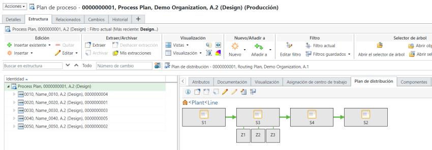
Default value. The zone is placed on the first level of the workstation. For example, zones Z1, Z2 and, Z3 are present on the first level of station S3.  |
||
|
2
|
The zone is placed on the second level of the workstation. For example, zone Z1 is present on the second level of station S3. 
|
|
|
Out of the box, you can add three zones on a level. Also, out of the box, the system allows you add two levels. However, you can configure the level settings to add a third level. That means you can add maximum nine zones on each side of a station. For more information, see Adding a Zone in the Routing Plan Tab.
|
• It is not binding to use the Side and Level attributes.
• The Level attribute is not applicable to a feeder line.
Consider that the following structure is present in the Manufacturing Resource Browser:

Station S3 has three zones, Z1, Z2 and Z3 present under it. Consider the different scenarios related to the positioning of zone Z1 when you set different values for the Side and Level attributes.
Value of Side Attribute | Value of Level Attribute | Location Description | ||
|---|---|---|---|---|
Null | 1 |  | ||
Left | 1 |  | ||
Right | 1 |  | ||
Right | 2 |  | ||
Left | 2 |
Consider the following structure:  In the following case, no zone is present on level 1 on the left side. For zone S1, after you set the value of the Side attribute as Left and the Level attribute as 2, the system displays zone Z1 on the first level because no zone already exists on the first level.  The following structure appears when you set the value of the Level attribute of zone Z2 as 1 and Z1 as 2.  |