Process Plan Flow Tab
The process plan flow diagram is available in the process plan browser to improve the user experience and the decision-making process. Use the Process Plan Flow tab in the Process Plan Browser (PPB) to view a graphical representation of a process plan. This representation includes the following entities:
• Starting point
• Operations
• Sequences
• Ending point
The system analyses the entities present in the process plan tree structure and creates the process plan flow diagram.
For more information, see Creating Graphical Representations in the Process Plan Flow Tab
Available Actions
The following table explains the actions available in the Process Plan Flow tab:
Action | Description | ||||
|---|---|---|---|---|---|
 Refresh Refresh | Refreshes the Process Plan Flow tab. | ||||
 Zoom In Zoom In | Zoom in on a selected area. | ||||
 Zoom Out Zoom Out | Zoom out of a selected area. | ||||
 Zoom Fit to Window Zoom Fit to Window | Re-sizes all images to fit the window. | ||||
 Toggle the setting for the automatic selection Toggle the setting for the automatic selection | Specifies the selection behavior between the process plan tree structure and the objects in the Process Plan Flow tab. Contains a menu with the following choices: • Auto select from Structure to Process Plan Flow – When checked, selecting an object in the process plan tree structure highlights the corresponding object in the Process Plan Flow tab.
• Auto select from Process Plan Flow to Structure – When checked, selecting an object in the Process Plan Flow tab highlights the corresponding object in the process plan tree structure.
| ||||
 Maximize Maximize | Maximizes the Process Plan Flow tab.
|
 Minimize
Symbols in Process Plan Flow Tab
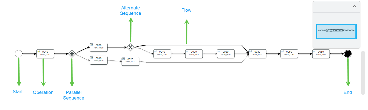
The following symbols appear in the tab:
Action | Significance | Available Right-click Actions | ||||
|---|---|---|---|---|---|---|
Start | An event that signifies start of the flow. | Insert Operations — Use this action to add operations after the start symbol. | ||||
End | An event that signifies the end of the flow. | None | ||||
Operation | An activity that signifies an operation
| • Insert Operations After — Use this action to add operations after the selected operation. • Remove — Use this action to remove the selected operation.
• Insert New Multiple Sequence—Use this action to create parallel or alternate sequences within a process plan. For more information, see Inserting Multiple Sequences in Process Plan Flow Tab. | ||||
Parallel Sequence | A gateway that signifies a parallel sequence | None | ||||
Alternate Sequence | A gateway that signifies an alternate sequence | None | ||||
Flow | Sequence flow
| None |
Features
• Operations and Sequences — The tab shows operations and sequences, but only the first level of operations is displayed by default.
• Parallel and Alternate Sequences — The tab supports both parallel and alternate sequences, which can coexist in a single process plan.
• Right-click menu actions — Actions like inserting and removing operations are available from the right-click menu for operations, but not for sequences.
• Drag and drop — The feature allows resequencing of operations by dragging and dropping them within the flow.
• Breadcrumb navigation — Breadcrumbs are used to navigate through different levels of operations and sequences.
• You can create sequences that branch from a parent sequence and then return to it. This flexibility helps in defining more complex process plans. You can create sequences that branch from one operation and return to another, even if they are at different levels.
• You must ensure that the return operations are higher than the branching operations to avoid logical errors. • The system also checks for valid part allocations within alternate sequences. |
Key Points
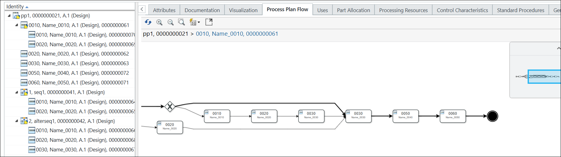
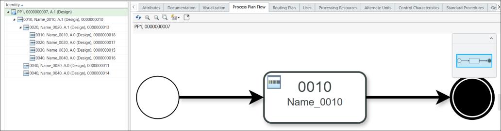
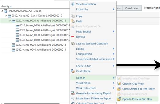
• The Process Plan Flow tab displays the operation information up to the first level. If you want to see the next level operation flow diagram in the Process Plan Flow tab, select the operation in the process plan tree structure. Right-click and select > . The system opens the operation flow diagram in the Process Plan Flow tab.
Consider the following scenario:
Operation 0010 is present under the process plan PP1. It is displayed in the Process Plan Flow tab. Operations 0020, 0030, and 0040 are present under the operation 0010. Multiple sub-operations are present under the operation 0020.
To view the flow diagram for operation 0020, select the operation 0020 in the Process Plan Flow tab. Right click and select > .
The flow diagram for the operation 0020 is displayed in the Process Plan Flow tab.
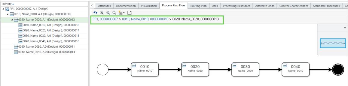
You can use the breadcrumbs to navigate to the desired entity as per your business requirement.
For more information, see Creating Graphical Representations in the Process Plan Flow Tab.
• Resequencing Operations — You can resequence operations by dragging and dropping them within the flow. When you resequence, the operation labels are also updated. You can resequence all the operations except the operations that act as branching or return operations.
You can drop operations in the following scenarios:
◦ Between two operations
◦ From a process plan to a sequence
◦ From a sequence to an operation
◦ From one sequence to another
◦ Across different hierarchical levels
• When you resequence one or more operations, the system also updates the PPB tree structure. • You can resequence multiple operations in the Process Plan Flow by selecting them with the Ctrl key or by drawing a selection rectangle around them. Once selected, drag the operations over the connector where you want to insert them. As you hover the pointer over the connector, it is highlighted, and you can now drop the operations in place. The system displays the updated structure in the Process Plan Flow tab. |
• A process plan can include multiple entities. When this occurs, the Process Plan Flow tab displays all associated entities within a flow diagram. To navigate between these entities, use the small blue window located in the top-right corner of the Process Plan Flow tab. This window acts as a mini-map, allowing you to explore different parts of the flow diagram. Click and drag the blue rectangle within the window to shift your view and focus on different entities in the diagram.
• In the Process Plan Flow tab, when you select an entity, the system visually highlights it by outlining its border in green, making it easy to identify the selected item within the flow diagram.
• The system highlights newly added operations by outlining their borders in blue, making them easily distinguishable within the flow diagram.
• You can change the position of the Process Plan Flow tab.
• Use of branching and return operations in Process Plan Flow tab as follows:
◦ You can branch off or return to the main sequence at any point while working with sub-sequences.
◦ When creating a sequence under a parent sequence, you have the flexibility to branch from any operation within that parent sequence, or even from the exact point where the parent sequence branched out.
◦ To return, you can choose any operation within the parent sequence, as long as it falls before or at the point where the parent sequence is returning.
◦ However, if branching and returning occur at different hierarchical levels, you cannot use the branching operation of the current parent sequence as your return point.
◦ For parallel sequences, only the left-out parts are available for allocations.
◦ The system also checks for valid part allocations within alternate sequences.
◦ When selecting branching or return operations, the drop-down menu also displays a reference to the sequence to which it belongs. Specifically, each branching or return operation starts with its label, followed by the identity of its parent sequence. This helps you quickly understand where each operation fits within the overall structure, making it easier to choose the right one, especially when you are working with complex or nested sequences.